100%
EG–129
ENGINE – ENGINE MECHANICAL
ENGINE INSTALLATION (2JZ–GTE)
1. INSTALL ENGINE AND TRANSMISSION ASSEMBLY IN VEHICLE
(a) Attach the engine hoist chain to the engine hangers.
(b) Lower the engine and transmission assembly into the engine compartment.
NOTICE: Install the engine and transmission assembly carefully without damaging the shift lever retainer (M/T), A/C compressor and PS solenoid valve.
(c) Insert the stud bolts of the front engine mounting insulators into the stud bolt holes of the front suspension crossmember.
(d) Temporarily install the 2 nuts holding the engine front mounting insulators to the front suspension crossmember.
(e) Keep the engine level with a jack.
(f) Remove the hoist chain.
P11499
P11500
P11526
(g) Temporarily install the support member to the engine rear mounting insulator with the 4 nuts.
(h) Install the 4 bolts holding the support member to the body.
Torque: 25 N·m (260 kgf·cm, 19 ft·lbf)
(i) Tighten the 4 nuts holding the support member to the engine rear mounting insulator.
Torque: 13 N·m (135 kgf·cm, 10 ft·lbf)
P11538
(j) Tighten the 2 nuts holding the engine front mounting insulators to the front suspension crossmember.
Torque: 59 N·m (600 kgf·cm, 43 ft·lbf)
2. M/T:
INSTALL TRANSMISSION SHIFT LEVER
Torque: 19 N·m (195 kgf·cm, 14 ft·lbf)
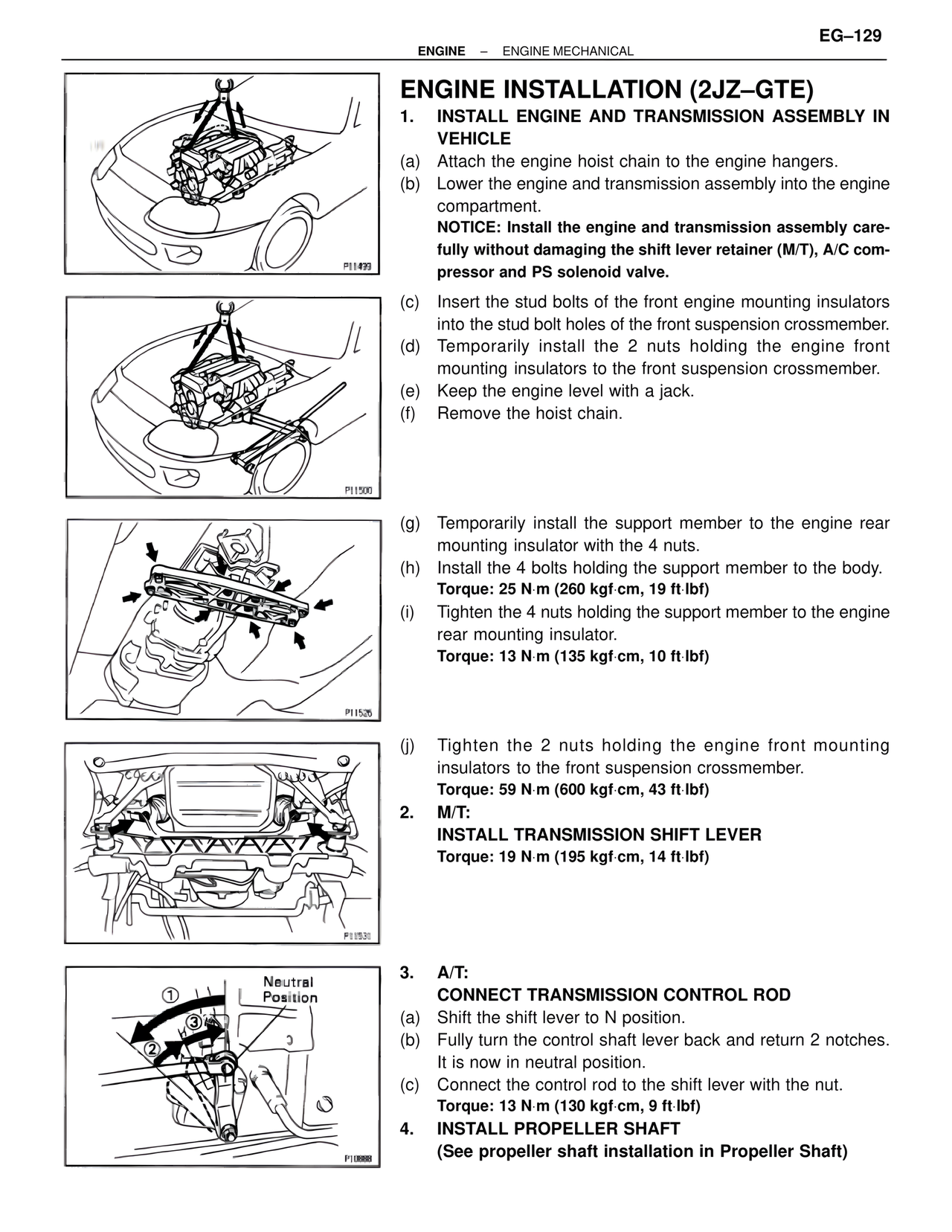
3. A/T:
CONNECT TRANSMISSION CONTROL ROD
(a) Shift the shift lever to N position.
(b) Fully turn the control shaft lever back and return 2 notches. It is now in neutral position.
(c) Connect the control rod to the shift lever with the nut.
Torque: 13 N·m (130 kgf·cm, 9 ft·lbf)
4. INSTALL PROPELLER SHAFT
(See propeller shaft installation in Propeller Shaft)
Neutral Position
1
3
2
P10888