100%
EG–58
ENGINE – ENGINE MECHANICAL
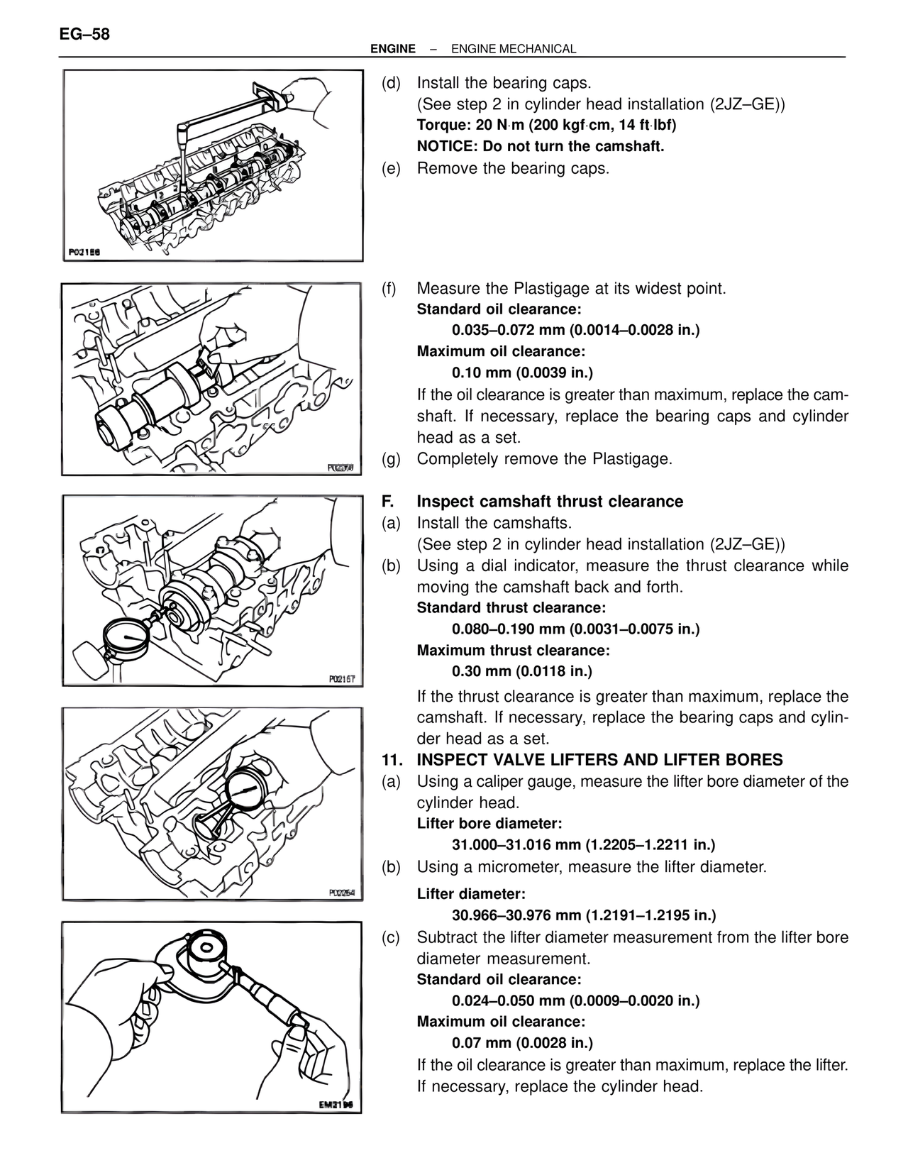
(d) Install the bearing caps.
(See step 2 in cylinder head installation (2JZ–GE))
Torque: 20 N·m (200 kgf·cm, 14 ft·lbf)
NOTICE: Do not turn the camshaft.
(e) Remove the bearing caps.
(f) Measure the Plastigage at its widest point.
Standard oil clearance:
0.035–0.072 mm (0.0014–0.0028 in.)
Maximum oil clearance:
0.10 mm (0.0039 in.)
If the oil clearance is greater than maximum, replace the camshaft. If necessary, replace the bearing caps and cylinder head as a set.
(g) Completely remove the Plastigage.
F. Inspect camshaft thrust clearance
(a) Install the camshafts.
(See step 2 in cylinder head installation (2JZ–GE))
(b) Using a dial indicator, measure the thrust clearance while moving the camshaft back and forth.
Standard thrust clearance:
0.080–0.190 mm (0.0031–0.0075 in.)
Maximum thrust clearance:
0.30 mm (0.0118 in.)
If the thrust clearance is greater than maximum, replace the camshaft. If necessary, replace the bearing caps and cylinder head as a set.
11. INSPECT VALVE LIFTERS AND LIFTER BORES
(a) Using a caliper gauge, measure the lifter bore diameter of the cylinder head.
Lifter bore diameter:
31.000–31.016 mm (1.2205–1.2211 in.)
(b) Using a micrometer, measure the lifter diameter.
Lifter diameter:
30.966–30.976 mm (1.2191–1.2195 in.)
(c) Subtract the lifter diameter measurement from the lifter bore diameter measurement.
Standard oil clearance:
0.024–0.050 mm (0.0009–0.0020 in.)
Maximum oil clearance:
0.07 mm (0.0028 in.)
If the oil clearance is greater than maximum, replace the lifter. If necessary, replace the cylinder head.
P02188
P02268
P02157
P02264
EM2196