100%
EG–68
ENGINE – ENGINE MECHANICAL
19. INSTALL WATER BYPASS OUTLET AND NO.1 WATER BYPASS PIPE
(See step 3 in water pump installation in Cooling System)
20. INSTALL TIMING BELT
(See steps 11 to 17 in timing belt removal)
21. INSTALL SPARK PLUGS
22. INSTALL DISTRIBUTOR AND CORDS ASSEMBLY
(See steps 2, 3 and 5 in distributor installation in Ignition System)
23. CONNECT HIGH–TENSION CORDS TO CYLINDER HEAD COVERS
(See step 1 in high–tension cords and cord clamps installation in Ignition System)
24. INSTALL NO.3 TIMING BELT COVER
25. INSTALL CYLINDER HEAD REAR COVER
26. INSTALL NO.2 VACUUM PIPE AND VSV ASSEMBLY
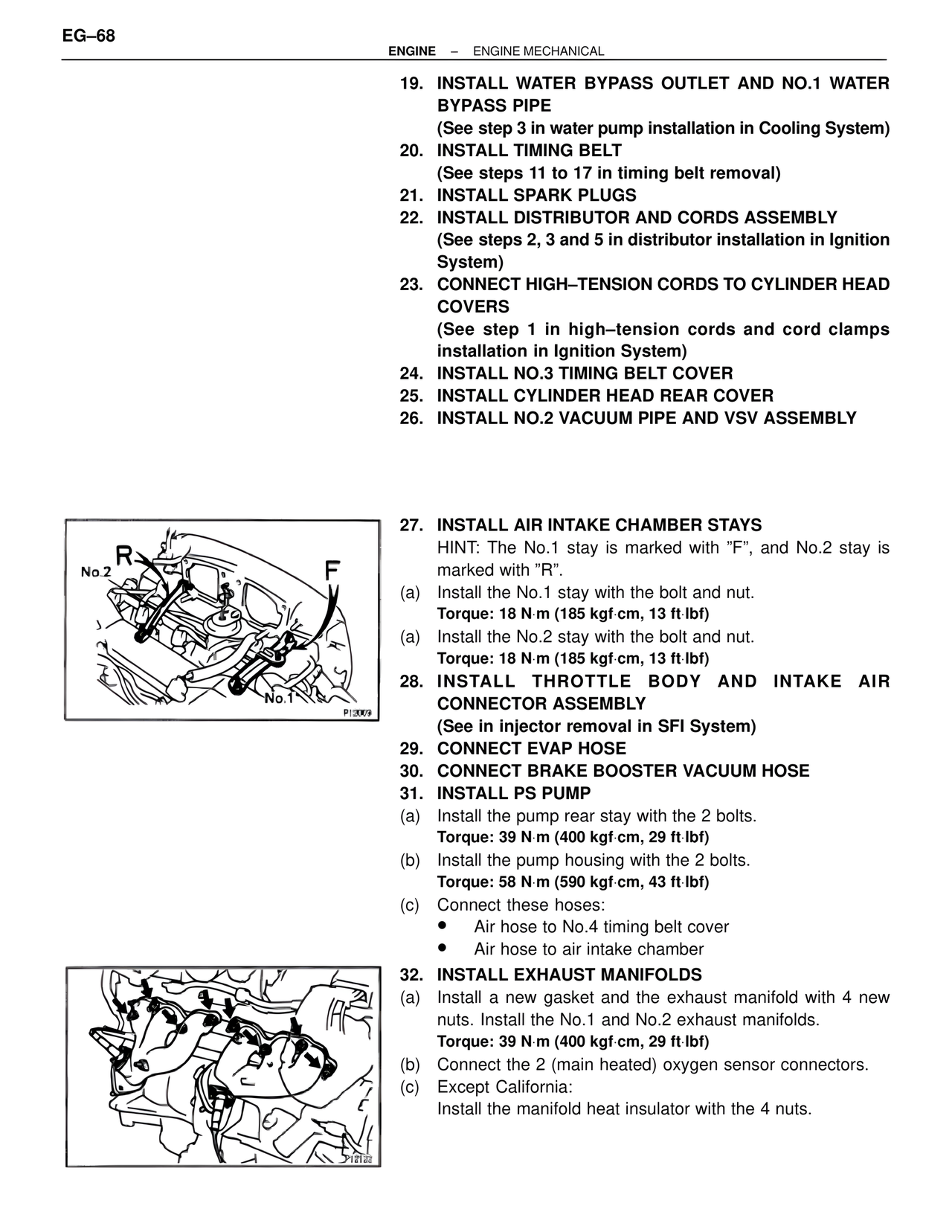
27. INSTALL AIR INTAKE CHAMBER STAYS
HINT: The No.1 stay is marked with "F", and No.2 stay is marked with "R".
(a) Install the No.1 stay with the bolt and nut.
Torque: 18 N·m (185 kgf·cm, 13 ft·lbf)
(a) Install the No.2 stay with the bolt and nut.
Torque: 18 N·m (185 kgf·cm, 13 ft·lbf)
28. INSTALL THROTTLE BODY AND INTAKE AIR CONNECTOR ASSEMBLY
(See in injector removal in SFI System)
29. CONNECT EVAP HOSE
30. CONNECT BRAKE BOOSTER VACUUM HOSE
31. INSTALL PS PUMP
(a) Install the pump rear stay with the 2 bolts.
Torque: 39 N·m (400 kgf·cm, 29 ft·lbf)
(b) Install the pump housing with the 2 bolts.
Torque: 58 N·m (590 kgf·cm, 43 ft·lbf)
(c) Connect these hoses:
• Air hose to No.4 timing belt cover
• Air hose to air intake chamber
32. INSTALL EXHAUST MANIFOLDS
(a) Install a new gasket and the exhaust manifold with 4 new nuts. Install the No.1 and No.2 exhaust manifolds.
Torque: 39 N·m (400 kgf·cm, 29 ft·lbf)
(b) Connect the 2 (main heated) oxygen sensor connectors.
(c) Except California:
Install the manifold heat insulator with the 4 nuts.
R
No.2
F
No.1
P12009
P12122