100%
EG–99
ENGINE – ENGINE MECHANICAL
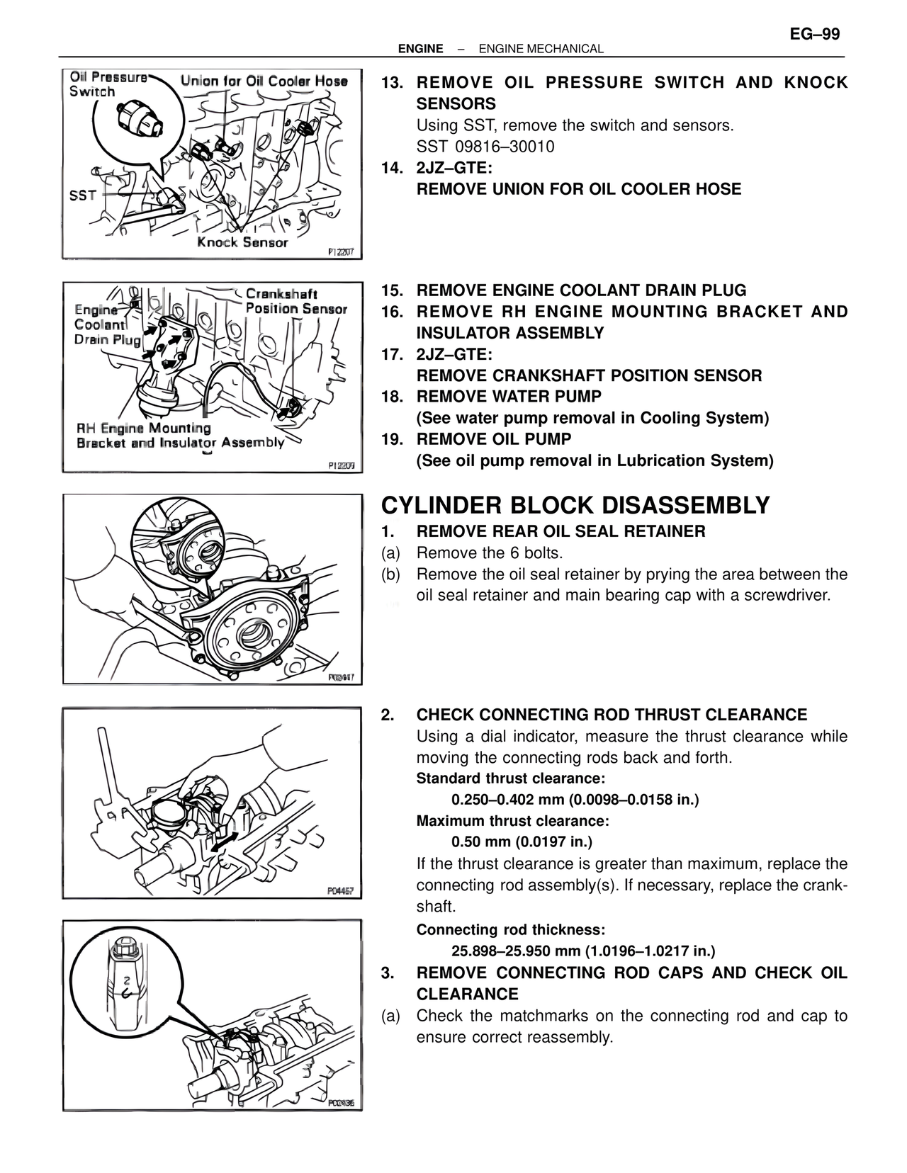
Oil Pressure Switch
Union for Oil Cooler Hose
SST
Knock Sensor
P12207
13. REMOVE OIL PRESSURE SWITCH AND KNOCK SENSORS
Using SST, remove the switch and sensors.
SST 09816–30010
14. 2JZ–GTE:
REMOVE UNION FOR OIL COOLER HOSE
Engine Coolant Drain Plug
Crankshaft Position Sensor
RH Engine Mounting Bracket and Insulator Assembly
P12209
15. REMOVE ENGINE COOLANT DRAIN PLUG
16. REMOVE RH ENGINE MOUNTING BRACKET AND INSULATOR ASSEMBLY
17. 2JZ–GTE:
REMOVE CRANKSHAFT POSITION SENSOR
18. REMOVE WATER PUMP
(See water pump removal in Cooling System)
19. REMOVE OIL PUMP
(See oil pump removal in Lubrication System)
P02447
CYLINDER BLOCK DISASSEMBLY
1. REMOVE REAR OIL SEAL RETAINER
(a) Remove the 6 bolts.
(b) Remove the oil seal retainer by prying the area between the oil seal retainer and main bearing cap with a screwdriver.
P04457
2. CHECK CONNECTING ROD THRUST CLEARANCE
Using a dial indicator, measure the thrust clearance while moving the connecting rods back and forth.
Standard thrust clearance:
0.250–0.402 mm (0.0098–0.0158 in.)
Maximum thrust clearance:
0.50 mm (0.0197 in.)
If the thrust clearance is greater than maximum, replace the connecting rod assembly(s). If necessary, replace the crankshaft.
Connecting rod thickness:
25.898–25.950 mm (1.0196–1.0217 in.)
P02436
3. REMOVE CONNECTING ROD CAPS AND CHECK OIL CLEARANCE
(a) Check the matchmarks on the connecting rod and cap to ensure correct reassembly.