100%
EM-71
ENGINE MECHANICAL (2JZ-GTE) - CYLINDER BLOCK
EM0AO-02
DISASSEMBLY
1. M/T:
REMOVE FLYWHEEL
2. A/T:
REMOVE DRIVE PLATE
3. INSTALL ENGINE TO ENGINE STAND FOR
DISASSEMBLY
4. REMOVE GENERATOR
5. REMOVE TIMING BELT AND PULLEYS
(See page EM-15 )
6. REMOVE CYLINDER HEAD (See page EM-29 )
7. REMOVE OIL COOLER (See page LU-20 )
8. REMOVE NO.2 WATER BYPASS PIPE WITH HOSE
Remove the 2 bolts, 2 nuts, water bypass pipe and gasket.
9. REMOVE KNOCK SENSORS
Using SST, remove the switch and sensors.
SST 09816-30010
10. REMOVE OIL FILTER BRACKET
Remove the union bolt, gasket, oil filter bracket and O-ring.
11. REMOVE LH ENGINE MOUNTING BRACKET AND IN-
SULATOR ASSEMBLY
12. REMOVE FUEL PIPE SUPPORT
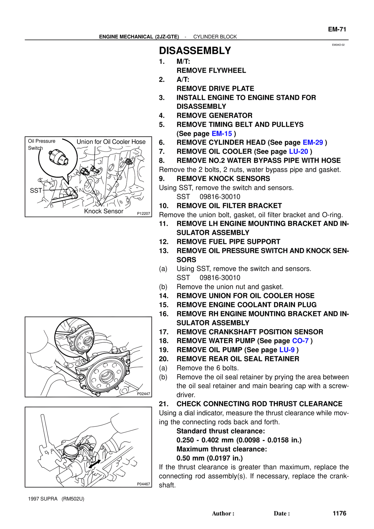
13. REMOVE OIL PRESSURE SWITCH AND KNOCK SEN-
SORS
(a) Using SST, remove the switch and sensors.
SST 09816-30010
(b) Remove the union nut and gasket.
14. REMOVE UNION FOR OIL COOLER HOSE
15. REMOVE ENGINE COOLANT DRAIN PLUG
16. REMOVE RH ENGINE MOUNTING BRACKET AND IN-
SULATOR ASSEMBLY
17. REMOVE CRANKSHAFT POSITION SENSOR
18. REMOVE WATER PUMP (See page CO-7 )
19. REMOVE OIL PUMP (See page LU-9 )
20. REMOVE REAR OIL SEAL RETAINER
(a) Remove the 6 bolts.
(b) Remove the oil seal retainer by prying the area between
the oil seal retainer and main bearing cap with a screw-
driver.
21. CHECK CONNECTING ROD THRUST CLEARANCE
Using a dial indicator, measure the thrust clearance while mov-
ing the connecting rods back and forth.
Standard thrust clearance:
0.250 - 0.402 mm (0.0098 - 0.0158 in.)
Maximum thrust clearance:
0.50 mm (0.0197 in.)
If the thrust clearance is greater than maximum, replace the
connecting rod assembly(s). If necessary, replace the crank-
shaft.
Oil Pressure
Switch
Union for Oil Cooler Hose
SST
Knock Sensor
P12207
P02447
P04467
1997 SUPRA (RM502U)
Author : Date : 1176