100%
EM-93
ENGINE MECHANICAL (2JZ-GTE) - CYLINDER BLOCK
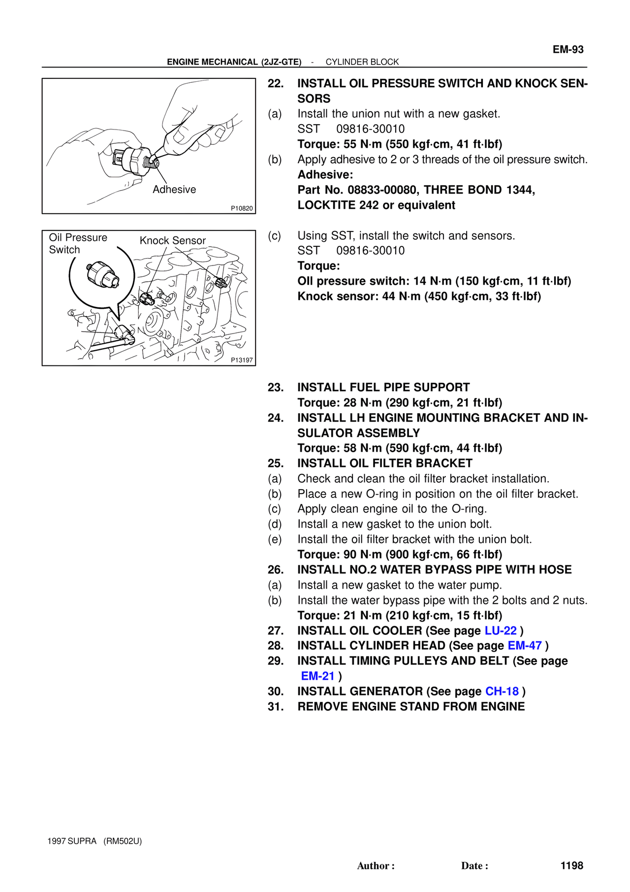
Adhesive
P10820
Oil Pressure
Switch
Knock Sensor
P13197
22. INSTALL OIL PRESSURE SWITCH AND KNOCK SEN-
SORS
(a) Install the union nut with a new gasket.
SST 09816-30010
Torque: 55 N·m (550 kgf·cm, 41 ft·lbf)
(b) Apply adhesive to 2 or 3 threads of the oil pressure switch.
Adhesive:
Part No. 08833-00080, THREE BOND 1344,
LOCKTITE 242 or equivalent
(c) Using SST, install the switch and sensors.
SST 09816-30010
Torque:
Oil pressure switch: 14 N·m (150 kgf·cm, 11 ft·lbf)
Knock sensor: 44 N·m (450 kgf·cm, 33 ft·lbf)
23. INSTALL FUEL PIPE SUPPORT
Torque: 28 N·m (290 kgf·cm, 21 ft·lbf)
24. INSTALL LH ENGINE MOUNTING BRACKET AND IN-
SULATOR ASSEMBLY
Torque: 58 N·m (590 kgf·cm, 44 ft·lbf)
25. INSTALL OIL FILTER BRACKET
(a) Check and clean the oil filter bracket installation.
(b) Place a new O-ring in position on the oil filter bracket.
(c) Apply clean engine oil to the O-ring.
(d) Install a new gasket to the union bolt.
(e) Install the oil filter bracket with the union bolt.
Torque: 90 N·m (900 kgf·cm, 66 ft·lbf)
26. INSTALL NO.2 WATER BYPASS PIPE WITH HOSE
(a) Install a new gasket to the water pump.
(b) Install the water bypass pipe with the 2 bolts and 2 nuts.
Torque: 21 N·m (210 kgf·cm, 15 ft·lbf)
27. INSTALL OIL COOLER (See page LU-22 )
28. INSTALL CYLINDER HEAD (See page EM-47 )
29. INSTALL TIMING PULLEYS AND BELT (See page
EM-21 )
30. INSTALL GENERATOR (See page CH-18 )
31. REMOVE ENGINE STAND FROM ENGINE
1997 SUPRA (RM502U)
Author : Date : 1198