100%
IN–28
INTRODUCTION – HOW TO TROUBLESHOOT ECU CONTROLLED SYSTEMS
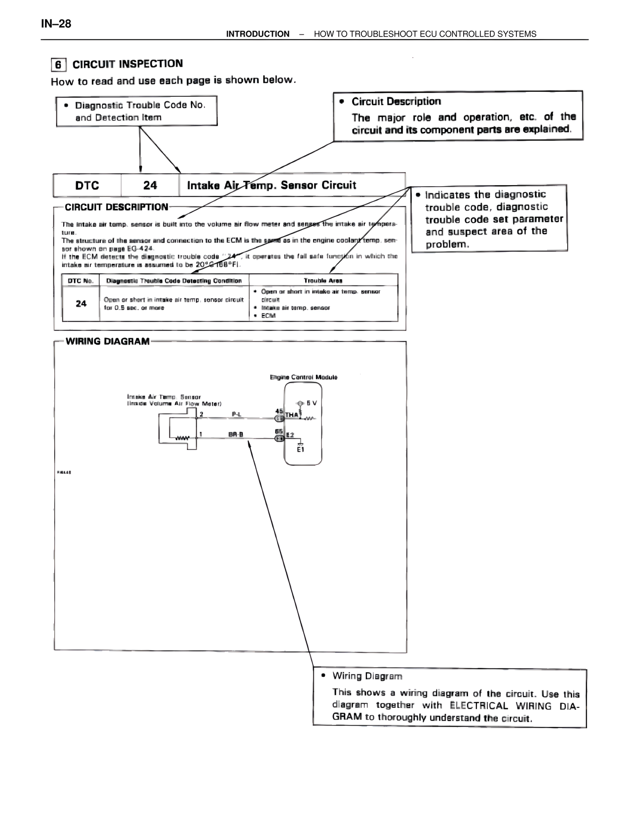
6 CIRCUIT INSPECTION
How to read and use each page is shown below.
• Diagnostic Trouble Code No.
and Detection Item
• Circuit Description
The major role and operation, etc. of the
circuit and its component parts are explained.
DTC 24 Intake Air Temp. Sensor Circuit
• Indicates the diagnostic
trouble code, diagnostic
trouble code set parameter
and suspect area of the
problem.
CIRCUIT DESCRIPTION
The intake air temp. sensor is built into the volume air flow meter and senses the intake air temperature.
The structure of the sensor and connection to the ECM is the same as in the engine coolant temp. sensor shown on page EG-424.
If the ECM detects the diagnostic trouble code "24", it operates the fail safe function in which the intake air temperature is assumed to be 20°C(68°F).
DTC No. | Diagnostic Trouble Code Detecting Condition | Trouble Area
24 | Open or short in intake air temp. sensor circuit for 0.5 sec. or more | • Open or short in intake air temp. sensor circuit
• Intake air temp. sensor
• ECM
WIRING DIAGRAM
Intake Air Temp. Sensor
(Inside Volume Air Flow Meter)
2 P-L
1 BR-B
Engine Control Module
⊕ 5V
45 THA
E3 +WA-
66 E2
E3
E1
F4648
• Wiring Diagram
This shows a wiring diagram of the circuit. Use this
diagram together with ELECTRICAL WIRING DIA-
GRAM to thoroughly understand the circuit.