100%
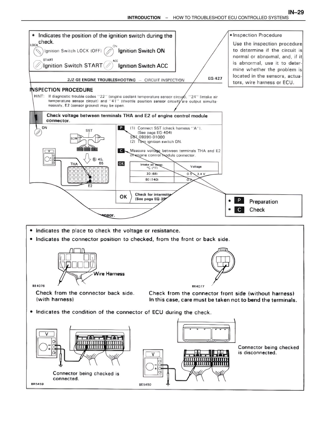
• Indicates the position of the ignition switch during the check.
LOCK
Ignition Switch LOCK (OFF)
ON
Ignition Switch ON
START
Ignition Switch START
ACC
Ignition Switch ACC
2JZ-GE ENGINE TROUBLESHOOTING — CIRCUIT INSPECTION
EG-427
INSPECTION PROCEDURE
HINT: If diagnostic trouble codes "22" (engine coolant temperature sensor circuit), "24" (intake air temperature sensor circuit) and "41" (throttle position sensor circuit) are output simultaneously, E2 (sensor ground) may be open.
Check voltage between terminals THA and E2 of engine control module connector.
ON
SST
ECM
V
B 45,
65
THA
E2
P (1) Connect SST (check harness "A").
(See page EG-404)
SST 09990-D1000
(2) Turn ignition switch ON.
C Measure voltage between terminals THA and E2 of engine control module connector.
OK
Intake air temp.
°C (°F) Voltage
20 (68) 0.5 - 3.4 V
80 (140) 0+
OK Check for intermitte...
(See page EG-39...)
...nsor.
• Inspection Procedure
Use the inspection procedure to determine if the circuit is normal or abnormal, and, if it is abnormal, use it to determine whether the problem is located in the sensors, actuators, wire harness or ECU.
• P Preparation
• C Check
• Indicates the place to check the voltage or resistance.
• Indicates the connector position to checked, from the front or back side.
BE4076
Wire Harness
Check from the connector back side. (with harness)
BE4077
Check from the connector front side (without harness)
In this case, care must be taken not to bend the terminals.
• Indicates the condition of the connector of ECU during the check.
BR5459
Connector being checked is connected.
BE5450
Connector being checked is disconnected.