100%
IN–31
INTRODUCTION – HOW TO TROUBLESHOOT ECU CONTROLLED SYSTEMS
Sensor Side
ECU Side
IN0379
ECU Side
Sensor Side
IN0378
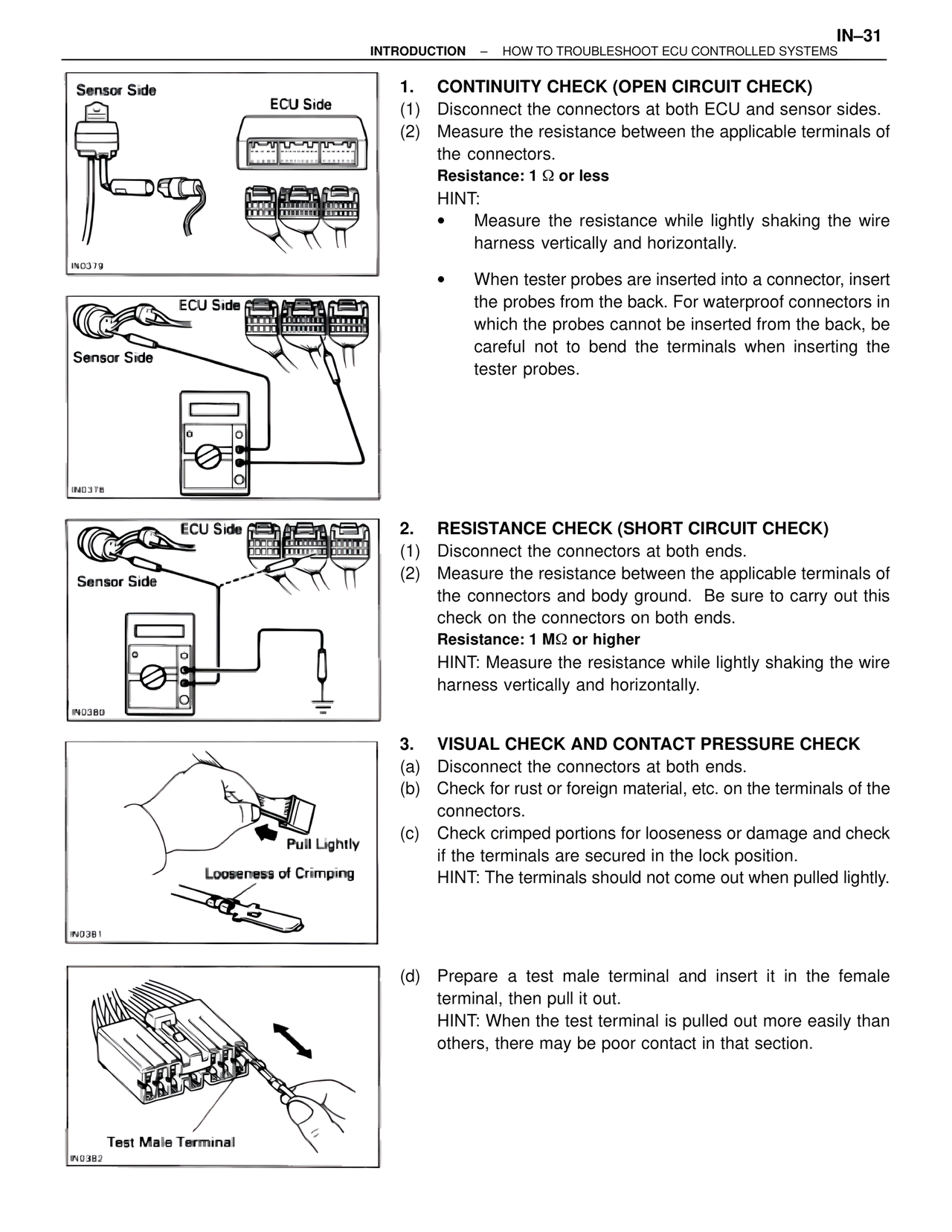
1. CONTINUITY CHECK (OPEN CIRCUIT CHECK)
(1) Disconnect the connectors at both ECU and sensor sides.
(2) Measure the resistance between the applicable terminals of
the connectors.
Resistance: 1 Ω or less
HINT:
• Measure the resistance while lightly shaking the wire
harness vertically and horizontally.
• When tester probes are inserted into a connector, insert
the probes from the back. For waterproof connectors in
which the probes cannot be inserted from the back, be
careful not to bend the terminals when inserting the
tester probes.
ECU Side
Sensor Side
IN0380
2. RESISTANCE CHECK (SHORT CIRCUIT CHECK)
(1) Disconnect the connectors at both ends.
(2) Measure the resistance between the applicable terminals of
the connectors and body ground. Be sure to carry out this
check on the connectors on both ends.
Resistance: 1 MΩ or higher
HINT: Measure the resistance while lightly shaking the wire
harness vertically and horizontally.
Pull Lightly
Looseness of Crimping
IN0381
3. VISUAL CHECK AND CONTACT PRESSURE CHECK
(a) Disconnect the connectors at both ends.
(b) Check for rust or foreign material, etc. on the terminals of the
connectors.
(c) Check crimped portions for looseness or damage and check
if the terminals are secured in the lock position.
HINT: The terminals should not come out when pulled lightly.
Test Male Terminal
IN0382
(d) Prepare a test male terminal and insert it in the female
terminal, then pull it out.
HINT: When the test terminal is pulled out more easily than
others, there may be poor contact in that section.