100%
IN–32
INTRODUCTION – HOW TO TROUBLESHOOT ECU CONTROLLED SYSTEMS
Actual examples of the inspection method for open circuit and short circuit are explained below.
1. OPEN CIRCUIT CHECK
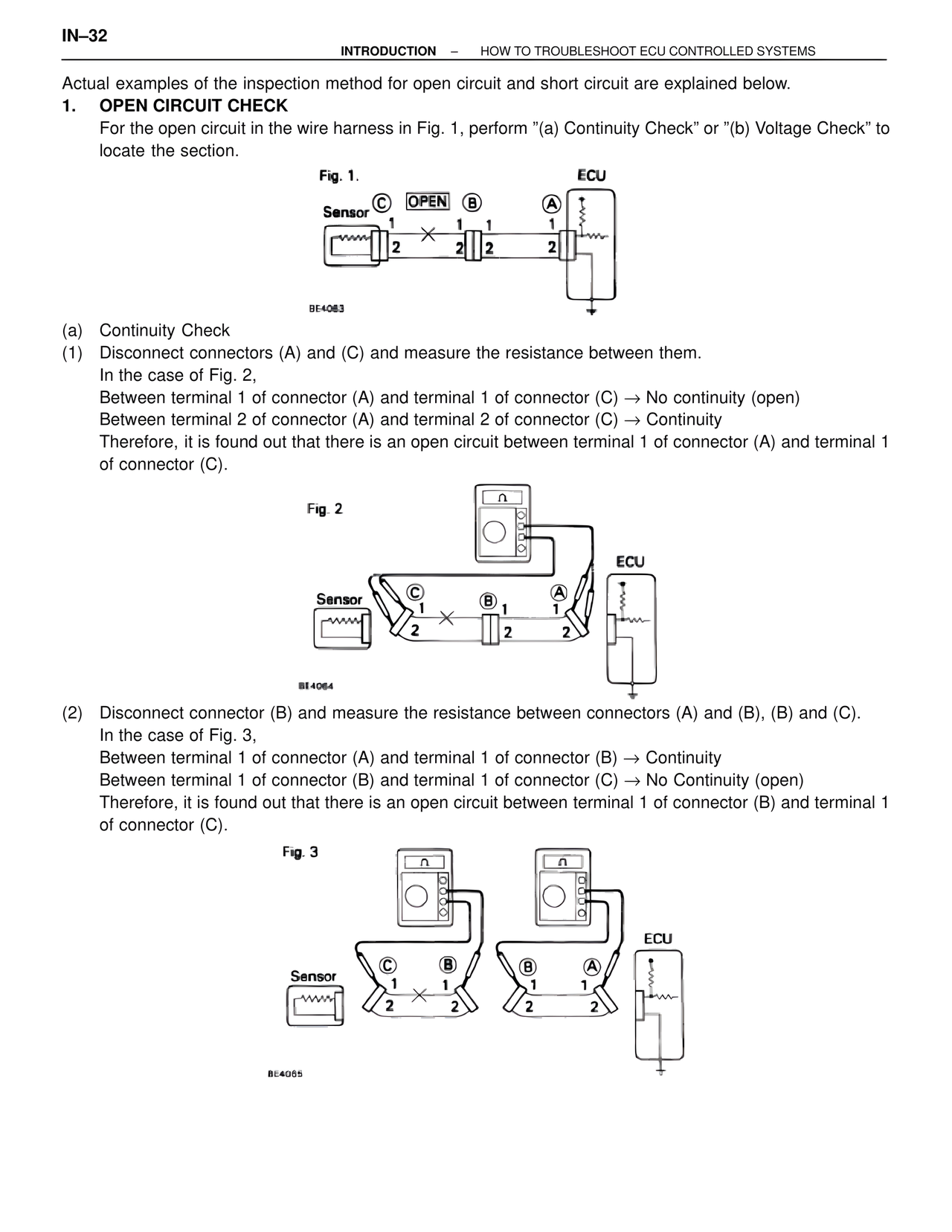
For the open circuit in the wire harness in Fig. 1, perform "(a) Continuity Check" or "(b) Voltage Check" to locate the section.
Fig. 1.
Sensor C OPEN B A ECU
1 1 1 1
2 2 2 2
BE4063
(a) Continuity Check
(1) Disconnect connectors (A) and (C) and measure the resistance between them.
In the case of Fig. 2,
Between terminal 1 of connector (A) and terminal 1 of connector (C) → No continuity (open)
Between terminal 2 of connector (A) and terminal 2 of connector (C) → Continuity
Therefore, it is found out that there is an open circuit between terminal 1 of connector (A) and terminal 1 of connector (C).
Fig. 2
Sensor C B A ECU
1 1 1
2 2 2
BE4064
(2) Disconnect connector (B) and measure the resistance between connectors (A) and (B), (B) and (C).
In the case of Fig. 3,
Between terminal 1 of connector (A) and terminal 1 of connector (B) → Continuity
Between terminal 1 of connector (B) and terminal 1 of connector (C) → No Continuity (open)
Therefore, it is found out that there is an open circuit between terminal 1 of connector (B) and terminal 1 of connector (C).
Fig. 3
Sensor C B B A ECU
1 1 1
2 2 2 2
BE4065