100%
IN–34
INTRODUCTION – HOW TO TROUBLESHOOT ECU CONTROLLED SYSTEMS
(a) Continuity Check with Ground
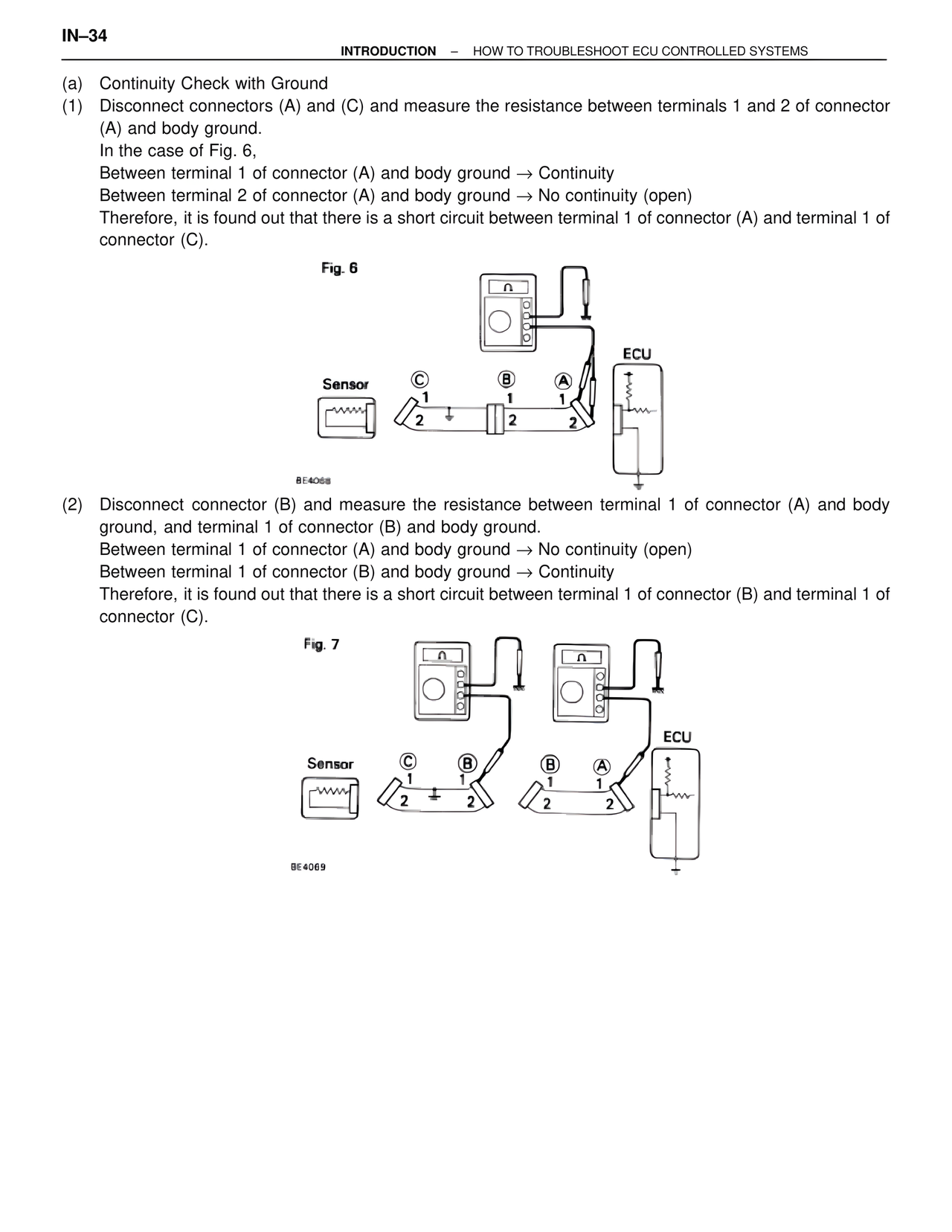
(1) Disconnect connectors (A) and (C) and measure the resistance between terminals 1 and 2 of connector
(A) and body ground.
In the case of Fig. 6,
Between terminal 1 of connector (A) and body ground → Continuity
Between terminal 2 of connector (A) and body ground → No continuity (open)
Therefore, it is found out that there is a short circuit between terminal 1 of connector (A) and terminal 1 of
connector (C).
Fig. 6
Sensor
C
1
2
B
1
2
A
1
2
ECU
BE4068
(2) Disconnect connector (B) and measure the resistance between terminal 1 of connector (A) and body
ground, and terminal 1 of connector (B) and body ground.
Between terminal 1 of connector (A) and body ground → No continuity (open)
Between terminal 1 of connector (B) and body ground → Continuity
Therefore, it is found out that there is a short circuit between terminal 1 of connector (B) and terminal 1 of
connector (C).
Fig. 7
Sensor
C
1
2
B
1
2
B
1
2
A
1
2
ECU
BE4069