100%
(b) Voltage Check
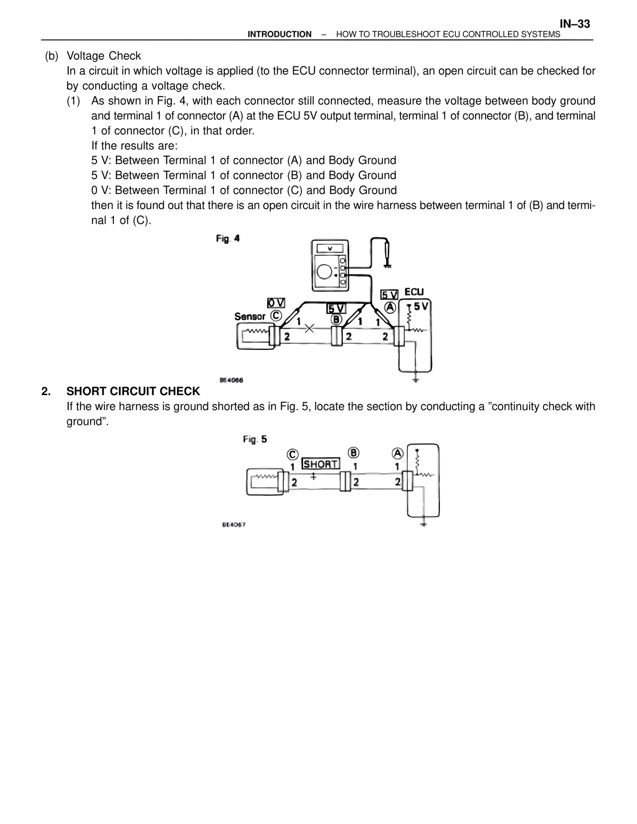
In a circuit in which voltage is applied (to the ECU connector terminal), an open circuit can be checked for
by conducting a voltage check.
(1) As shown in Fig. 4, with each connector still connected, measure the voltage between body ground
and terminal 1 of connector (A) at the ECU 5V output terminal, terminal 1 of connector (B), and terminal
1 of connector (C), in that order.
If the results are:
5 V: Between Terminal 1 of connector (A) and Body Ground
5 V: Between Terminal 1 of connector (B) and Body Ground
0 V: Between Terminal 1 of connector (C) and Body Ground
then it is found out that there is an open circuit in the wire harness between terminal 1 of (B) and termi-
nal 1 of (C).
Fig. 4
0V
5V
Sensor C
1
2
B
1
2
A
1
2
ECU
5V
5V
BE4066
2. SHORT CIRCUIT CHECK
If the wire harness is ground shorted as in Fig. 5, locate the section by conducting a "continuity check with
ground".
Fig. 5
C
1
2
SHORT
B
1
2
A
1
2
BE4067