100%
PR–15
PROPELLER SHAFT – PROPELLER SHAFT
SST
R06872
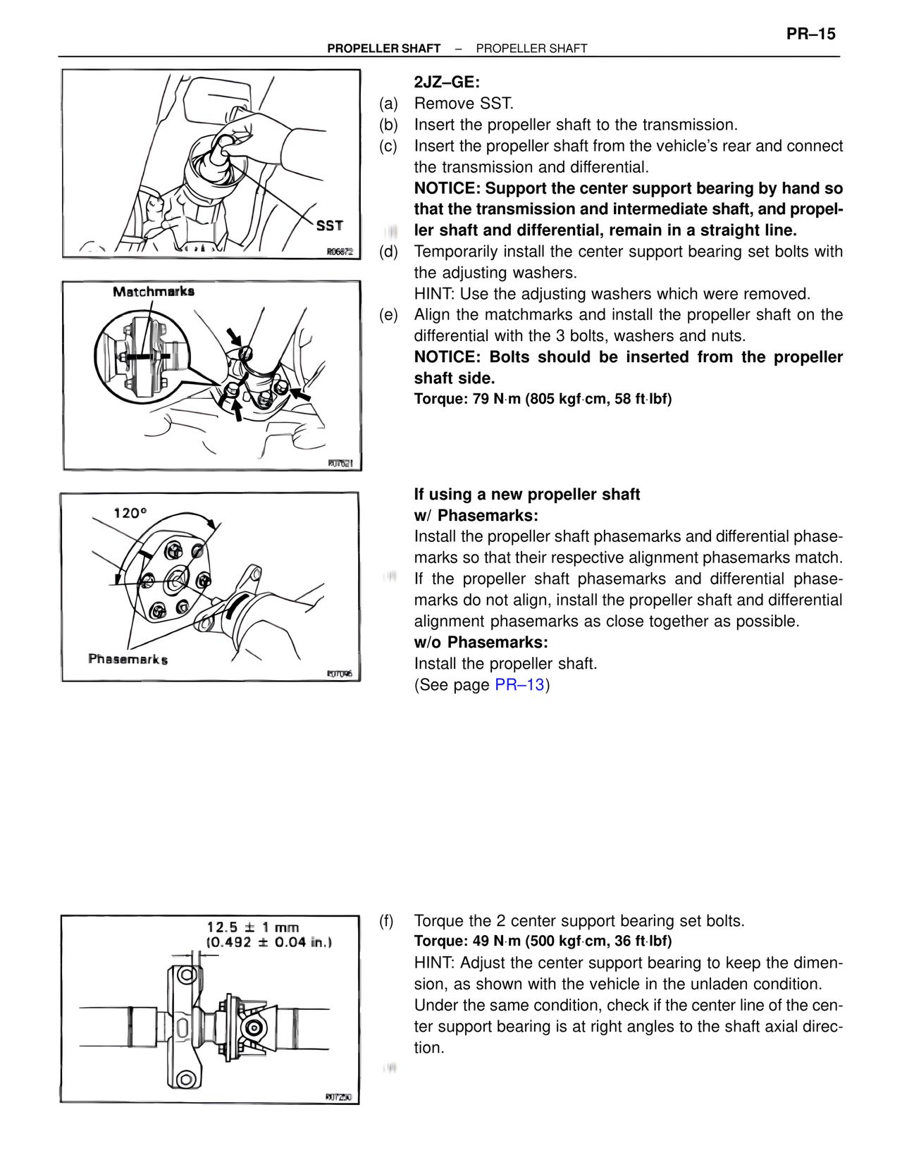
Matchmarks
R07621
120°
Phasemarks
E07096
12.5 ± 1 mm
(0.492 ± 0.04 in.)
R07Z50
2JZ–GE:
(a) Remove SST.
(b) Insert the propeller shaft to the transmission.
(c) Insert the propeller shaft from the vehicle's rear and connect
the transmission and differential.
NOTICE: Support the center support bearing by hand so
that the transmission and intermediate shaft, and propel-
ler shaft and differential, remain in a straight line.
(d) Temporarily install the center support bearing set bolts with
the adjusting washers.
HINT: Use the adjusting washers which were removed.
(e) Align the matchmarks and install the propeller shaft on the
differential with the 3 bolts, washers and nuts.
NOTICE: Bolts should be inserted from the propeller
shaft side.
Torque: 79 N·m (805 kgf·cm, 58 ft·lbf)
If using a new propeller shaft
w/ Phasemarks:
Install the propeller shaft phasemarks and differential phase-
marks so that their respective alignment phasemarks match.
If the propeller shaft phasemarks and differential phase-
marks do not align, install the propeller shaft and differential
alignment phasemarks as close together as possible.
w/o Phasemarks:
Install the propeller shaft.
(See page PR–13)
(f) Torque the 2 center support bearing set bolts.
Torque: 49 N·m (500 kgf·cm, 36 ft·lbf)
HINT: Adjust the center support bearing to keep the dimen-
sion, as shown with the vehicle in the unladen condition.
Under the same condition, check if the center line of the cen-
ter support bearing is at right angles to the shaft axial direc-
tion.