100%
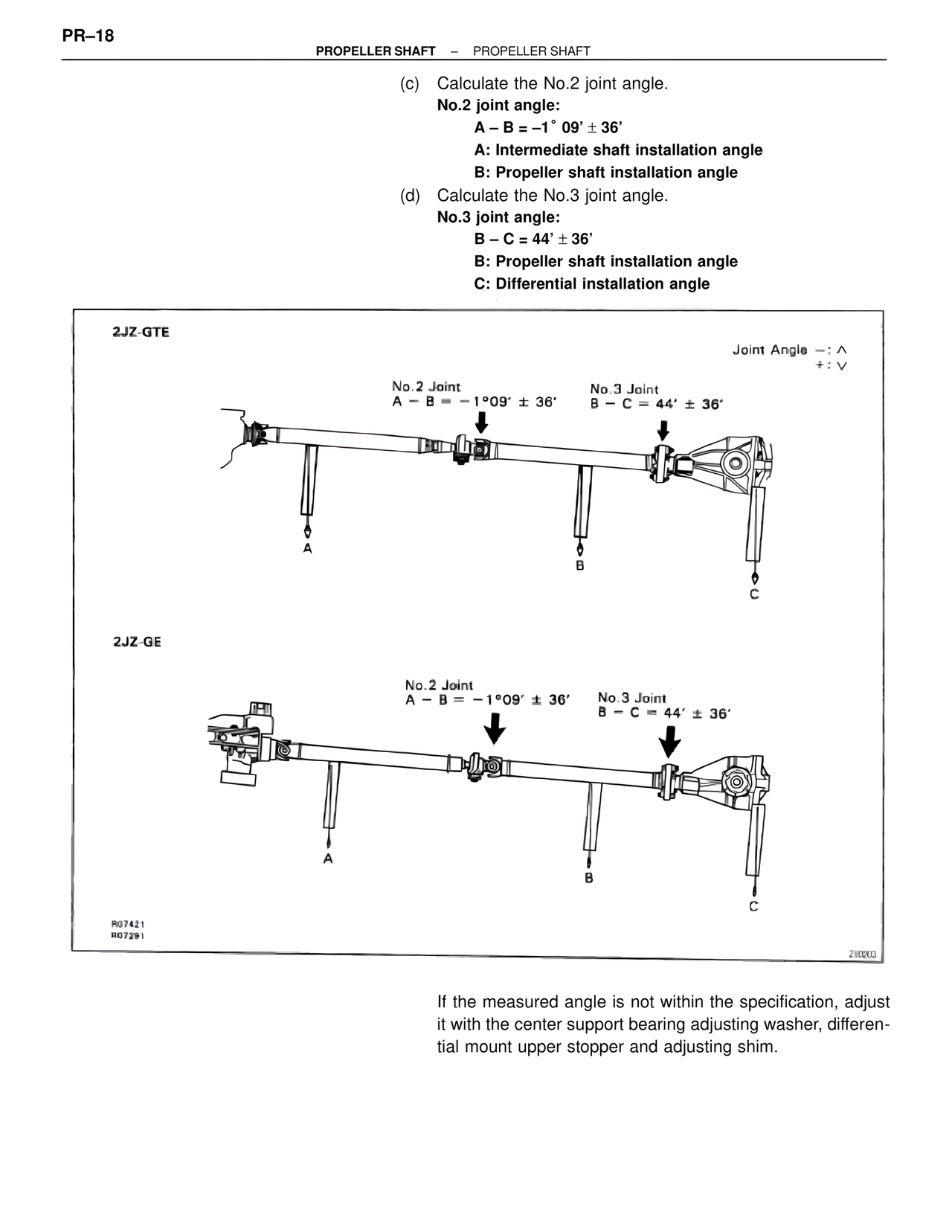
(c) Calculate the No.2 joint angle.
No.2 joint angle:
A – B = –1° 09' ± 36'
A: Intermediate shaft installation angle
B: Propeller shaft installation angle
(d) Calculate the No.3 joint angle.
No.3 joint angle:
B – C = 44' ± 36'
B: Propeller shaft installation angle
C: Differential installation angle
2JZ-GTE
Joint Angle –: ^
+: V
No.2 Joint
A – B = –1°09' ± 36'
No.3 Joint
B – C = 44' ± 36'
A
B
C
2JZ-GE
No.2 Joint
A – B = –1°09' ± 36'
No.3 Joint
B – C = 44' ± 36'
A
B
C
R07421
R07291
2J0003
If the measured angle is not within the specification, adjust it with the center support bearing adjusting washer, differential mount upper stopper and adjusting shim.