100%
SA–48
SUSPENSION AND AXLE – REAR DRIVE SHAFT
(e) Using a hammer, lightly tap the end of the drive shaft,
disengage the axle hub and remove the drive shaft.
NOTICE: Be careful not to damage the boots and speed
sensor rotor of the drive shaft, and oil seal of the axle
hub.
INSTALLATION NOTICE: Make sure the outboard joint
side of the drive shaft does not bend too much.
R06937
REAR DRIVE SHAFT DISASSEMBLY
1. CHECK DRIVE SHAFT
(a) Check that operation of the joint is smooth within the sliding
region in the axial direction.
HINT: If a large angle is used for the cross–groove type joint,
the joint will feel like it is catching, but this does not indicate
an abnormality.
(b) Check that the boots are not cracked, damaged or leaking.
(c) Check that there are no scratches on the speed sensor rotor.
R05813
2. REMOVE END COVER
(a) Using a screwdriver, remove the end cover.
(b) Use bolts, nuts and washers to keep the inboard joint
together.
NOTICE: Tighten the bolt by hand to avoid scratching the
flange surface.
R00195
3. REMOVE BOOT CLAMPS
Using a side cutter or pliers, remove the clamps.
P05814
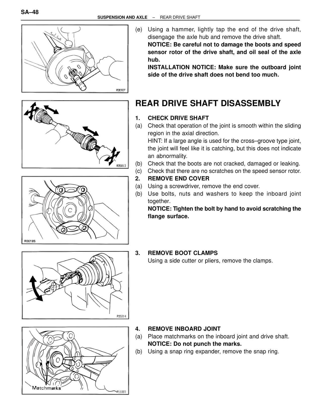
4. REMOVE INBOARD JOINT
(a) Place matchmarks on the inboard joint and drive shaft.
NOTICE: Do not punch the marks.
(b) Using a snap ring expander, remove the snap ring.
Matchmarks
P11003