100%
EG–236
ENGINE – SFI SYSTEM (2JZ–GE)
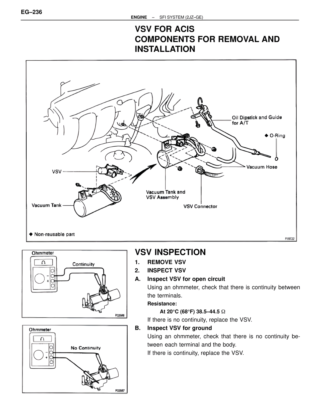
VSV FOR ACIS
COMPONENTS FOR REMOVAL AND
INSTALLATION
Oil Dipstick and Guide
for A/T
♦ O-Ring
Vacuum Hose
VSV
Vacuum Tank and
VSV Assembly
VSV Connector
Vacuum Tank
♦ Non-reusable part
P18722
VSV INSPECTION
1. REMOVE VSV
2. INSPECT VSV
A. Inspect VSV for open circuit
Using an ohmmeter, check that there is continuity between
the terminals.
Resistance:
At 20°C (68°F) 38.5–44.5 Ω
If there is no continuity, replace the VSV.
B. Inspect VSV for ground
Using an ohmmeter, check that there is no continuity be-
tween each terminal and the body.
If there is continuity, replace the VSV.
Ohmmeter
Continuity
P00566
Ohmmeter
No Continuity
P00567