100%
EG–276
ENGINE – SFI SYSTEM (2JZ–GTE)
(2)
(1)
Clamp
(3)
P11317
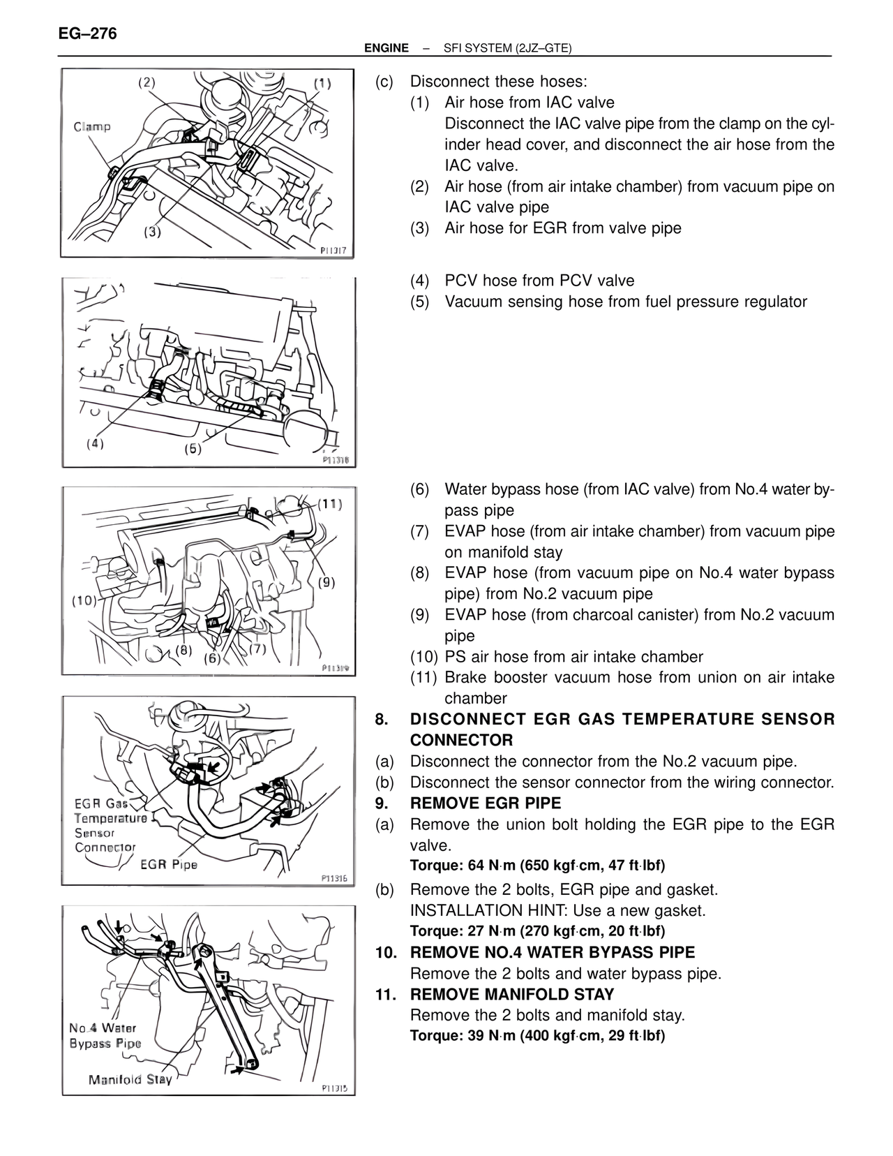
(c) Disconnect these hoses:
(1) Air hose from IAC valve
Disconnect the IAC valve pipe from the clamp on the cyl-
inder head cover, and disconnect the air hose from the
IAC valve.
(2) Air hose (from air intake chamber) from vacuum pipe on
IAC valve pipe
(3) Air hose for EGR from valve pipe
(4)
(5)
P11318
(4) PCV hose from PCV valve
(5) Vacuum sensing hose from fuel pressure regulator
(11)
(9)
(10)
(8) (7)
(6)
P11309
(6) Water bypass hose (from IAC valve) from No.4 water by-
pass pipe
(7) EVAP hose (from air intake chamber) from vacuum pipe
on manifold stay
(8) EVAP hose (from vacuum pipe on No.4 water bypass
pipe) from No.2 vacuum pipe
(9) EVAP hose (from charcoal canister) from No.2 vacuum
pipe
(10) PS air hose from air intake chamber
(11) Brake booster vacuum hose from union on air intake
chamber
EGR Gas
Temperature
Sensor
Connector
EGR Pipe
P11315
8. DISCONNECT EGR GAS TEMPERATURE SENSOR
CONNECTOR
(a) Disconnect the connector from the No.2 vacuum pipe.
(b) Disconnect the sensor connector from the wiring connector.
9. REMOVE EGR PIPE
(a) Remove the union bolt holding the EGR pipe to the EGR
valve.
Torque: 64 N·m (650 kgf·cm, 47 ft·lbf)
(b) Remove the 2 bolts, EGR pipe and gasket.
INSTALLATION HINT: Use a new gasket.
Torque: 27 N·m (270 kgf·cm, 20 ft·lbf)
10. REMOVE NO.4 WATER BYPASS PIPE
Remove the 2 bolts and water bypass pipe.
11. REMOVE MANIFOLD STAY
Remove the 2 bolts and manifold stay.
Torque: 39 N·m (400 kgf·cm, 29 ft·lbf)
No.4 Water
Bypass Pipe
Manifold Stay
P11315