100%
EG–277
ENGINE – SFI SYSTEM (2JZ–GTE)
Clamp
Ground
Cable
P11304
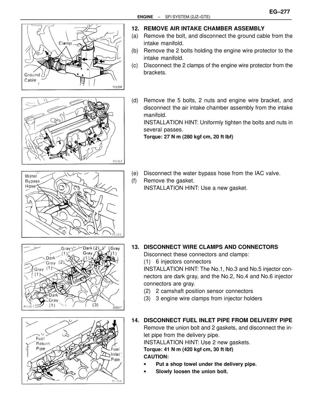
12. REMOVE AIR INTAKE CHAMBER ASSEMBLY
(a) Remove the bolt, and disconnect the ground cable from the
intake manifold.
(b) Remove the 2 bolts holding the engine wire protector to the
intake manifold.
(c) Disconnect the 2 clamps of the engine wire protector from the
brackets.
P11313
(d) Remove the 5 bolts, 2 nuts and engine wire bracket, and
disconnect the air intake chamber assembly from the intake
manifold.
INSTALLATION HINT: Uniformly tighten the bolts and nuts in
several passes.
Torque: 27 N·m (280 kgf·cm, 20 ft·lbf)
Water
Bypass
Hose
P11312
(e) Disconnect the water bypass hose from the IAC valve.
(f) Remove the gasket.
INSTALLATION HINT: Use a new gasket.
Gray Dark (2) Gray
(1) Gray (1)
Dark
Gray (2)
Gray (1)
Dark
Gray
(1)
P11311 (3)
Z09317
13. DISCONNECT WIRE CLAMPS AND CONNECTORS
Disconnect these connectors and clamps:
(1) 6 injectors connectors
INSTALLATION HINT: The No.1, No.3 and No.5 injector con-
nectors are dark gray, and the No.2, No.4 and No.6 injector
connectors are gray.
(2) 2 camshaft position sensor connectors
(3) 3 engine wire clamps from injector holders
Fuel
Return
Pipe
Fuel
Inlet
Pipe
P11300
14. DISCONNECT FUEL INLET PIPE FROM DELIVERY PIPE
Remove the union bolt and 2 gaskets, and disconnect the in-
let pipe from the delivery pipe.
INSTALLATION HINT: Use 2 new gaskets.
Torque: 41 N·m (420 kgf·cm, 30 ft·lbf)
CAUTION:
• Put a shop towel under the delivery pipe.
• Slowly loosen the union bolt.