100%
EG–292
ENGINE – SFI SYSTEM (2JZ–GTE)
Vacuum
Disconnect
Feeler
Gauge
P11989
Ohmmeter
VTA
VC
E2 IDL
Z09088
P11453
0.65 mm
P17005
Z09125
Ohmmeter
E2 IDL
Z09091
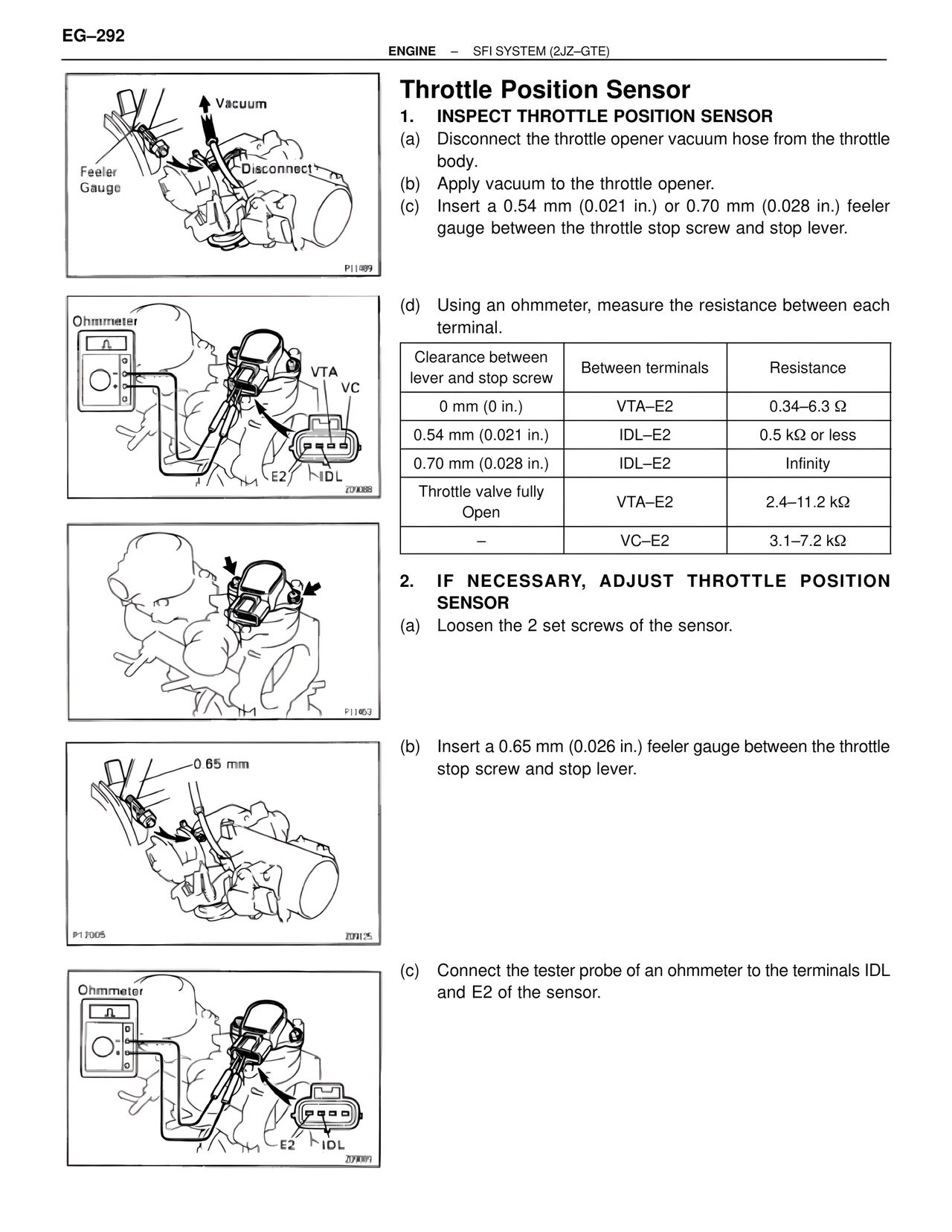
Throttle Position Sensor
1. INSPECT THROTTLE POSITION SENSOR
(a) Disconnect the throttle opener vacuum hose from the throttle body.
(b) Apply vacuum to the throttle opener.
(c) Insert a 0.54 mm (0.021 in.) or 0.70 mm (0.028 in.) feeler gauge between the throttle stop screw and stop lever.
(d) Using an ohmmeter, measure the resistance between each terminal.
Clearance between lever and stop screw | Between terminals | Resistance
0 mm (0 in.) | VTA–E2 | 0.34–6.3 Ω
0.54 mm (0.021 in.) | IDL–E2 | 0.5 kΩ or less
0.70 mm (0.028 in.) | IDL–E2 | Infinity
Throttle valve fully Open | VTA–E2 | 2.4–11.2 kΩ
– | VC–E2 | 3.1–7.2 kΩ
2. IF NECESSARY, ADJUST THROTTLE POSITION SENSOR
(a) Loosen the 2 set screws of the sensor.
(b) Insert a 0.65 mm (0.026 in.) feeler gauge between the throttle stop screw and stop lever.
(c) Connect the tester probe of an ohmmeter to the terminals IDL and E2 of the sensor.