100%
EG–307
ENGINE – SFI SYSTEM (2JZ–GTE)
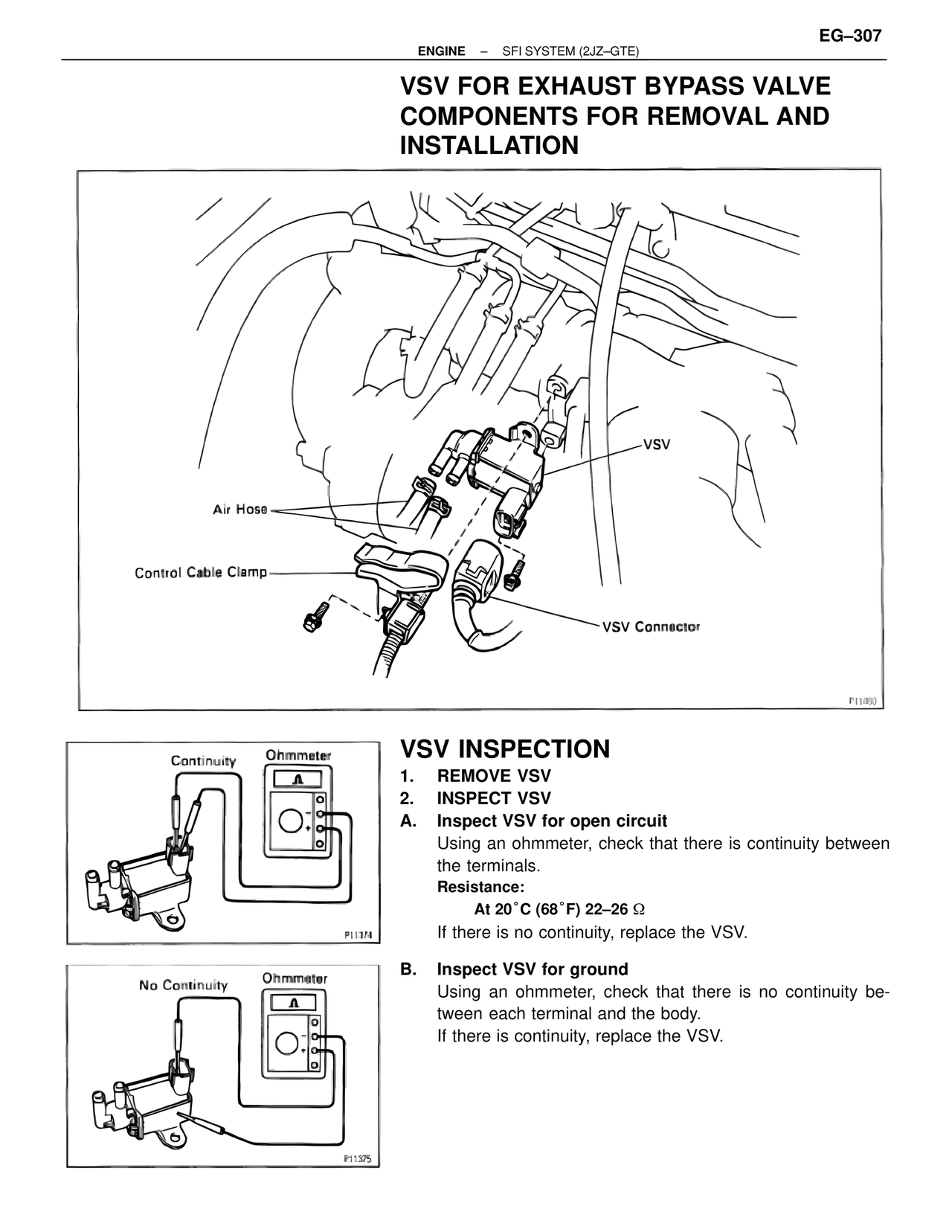
VSV FOR EXHAUST BYPASS VALVE
COMPONENTS FOR REMOVAL AND
INSTALLATION
Air Hose
Control Cable Clamp
VSV
VSV Connector
P11080
Continuity Ohmmeter
P1137N
No Continuity Ohmmeter
P11375
VSV INSPECTION
1. REMOVE VSV
2. INSPECT VSV
A. Inspect VSV for open circuit
Using an ohmmeter, check that there is continuity between
the terminals.
Resistance:
At 20°C (68°F) 22–26 Ω
If there is no continuity, replace the VSV.
B. Inspect VSV for ground
Using an ohmmeter, check that there is no continuity be-
tween each terminal and the body.
If there is continuity, replace the VSV.