100%
EG–315
ENGINE – SFI SYSTEM (2JZ–GTE)
2. INSPECT SUPPLY POWER OF TURBO PRESSURE SENSOR
(a) Disconnect the ECM from the ECU bracket.
(See steps 1 to 4 in ECM)
(b) Install SST (check harness) between the ECM and wiring connectors.
(See standard value of ECM terminals in Engine Troubleshooting)
SST 09990–01000
(c) Turn the ignition switch ON.
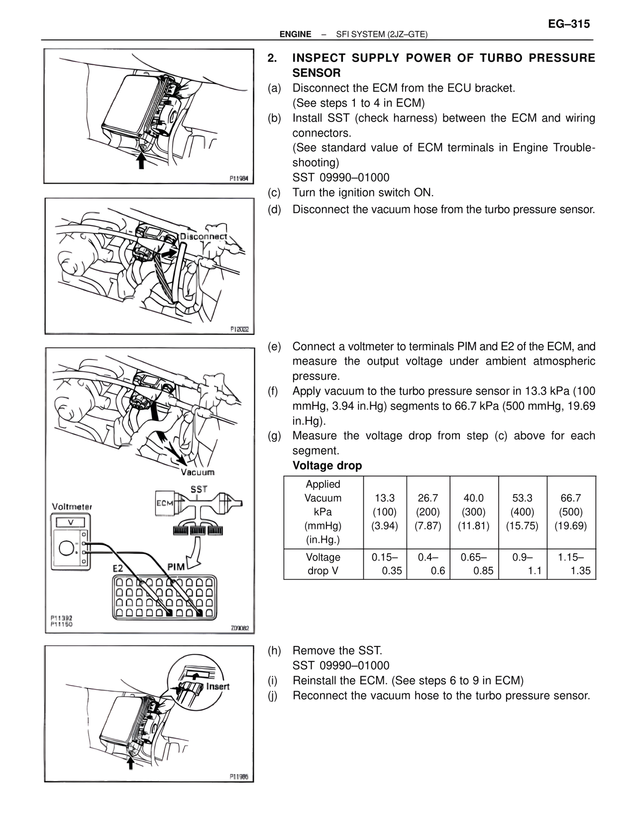
(d) Disconnect the vacuum hose from the turbo pressure sensor.
Disconnect
(e) Connect a voltmeter to terminals PIM and E2 of the ECM, and measure the output voltage under ambient atmospheric pressure.
(f) Apply vacuum to the turbo pressure sensor in 13.3 kPa (100 mmHg, 3.94 in.Hg) segments to 66.7 kPa (500 mmHg, 19.69 in.Hg).
(g) Measure the voltage drop from step (c) above for each segment.
Voltage drop
Applied Vacuum kPa (mmHg) (in.Hg.)
13.3 (100) (3.94)
26.7 (200) (7.87)
40.0 (300) (11.81)
53.3 (400) (15.75)
66.7 (500) (19.69)
Voltage drop V
0.15–0.35
0.4–0.6
0.65–0.85
0.9–1.1
1.15–1.35
Vacuum
SST
ECM
Voltmeter
E2 PIM
P11392
P11150
Z09082
(h) Remove the SST.
SST 09990–01000
(i) Reinstall the ECM. (See steps 6 to 9 in ECM)
(j) Reconnect the vacuum hose to the turbo pressure sensor.
Insert
P11984
P12022
P11386