100%
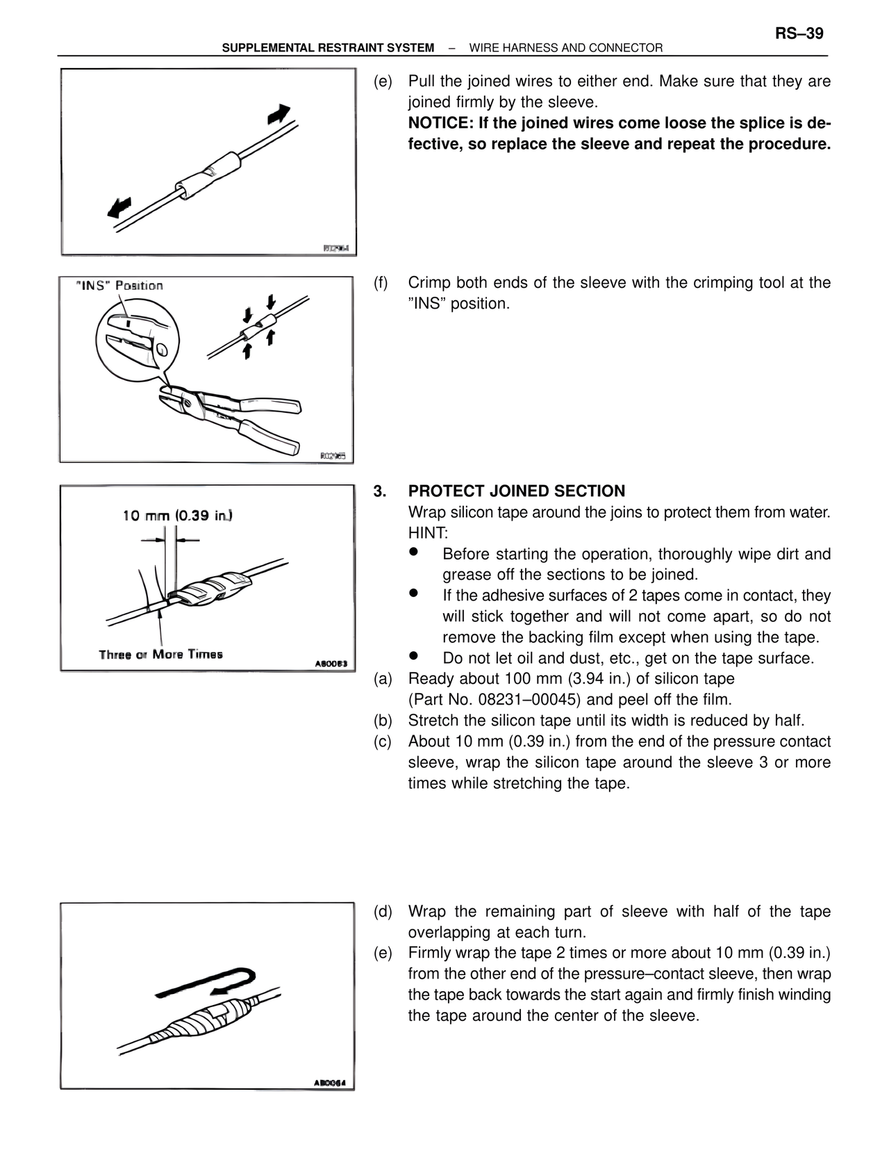
(e) Pull the joined wires to either end. Make sure that they are
joined firmly by the sleeve.
NOTICE: If the joined wires come loose the splice is de-
fective, so replace the sleeve and repeat the procedure.
R02964
"INS" Position
(f) Crimp both ends of the sleeve with the crimping tool at the
"INS" position.
R02965
10 mm (0.39 in.)
Three or More Times
A80063
3. PROTECT JOINED SECTION
Wrap silicon tape around the joins to protect them from water.
HINT:
• Before starting the operation, thoroughly wipe dirt and
grease off the sections to be joined.
• If the adhesive surfaces of 2 tapes come in contact, they
will stick together and will not come apart, so do not
remove the backing film except when using the tape.
• Do not let oil and dust, etc., get on the tape surface.
(a) Ready about 100 mm (3.94 in.) of silicon tape
(Part No. 08231–00045) and peel off the film.
(b) Stretch the silicon tape until its width is reduced by half.
(c) About 10 mm (0.39 in.) from the end of the pressure contact
sleeve, wrap the silicon tape around the sleeve 3 or more
times while stretching the tape.
A80064
(d) Wrap the remaining part of sleeve with half of the tape
overlapping at each turn.
(e) Firmly wrap the tape 2 times or more about 10 mm (0.39 in.)
from the other end of the pressure–contact sleeve, then wrap
the tape back towards the start again and firmly finish winding
the tape around the center of the sleeve.