← p.051p.053 →
SRS/Supplemental Restraint System — Circuit Inspection Dtc (Normal) Source Voltage Drop Circuit Description, page 52
52 / 102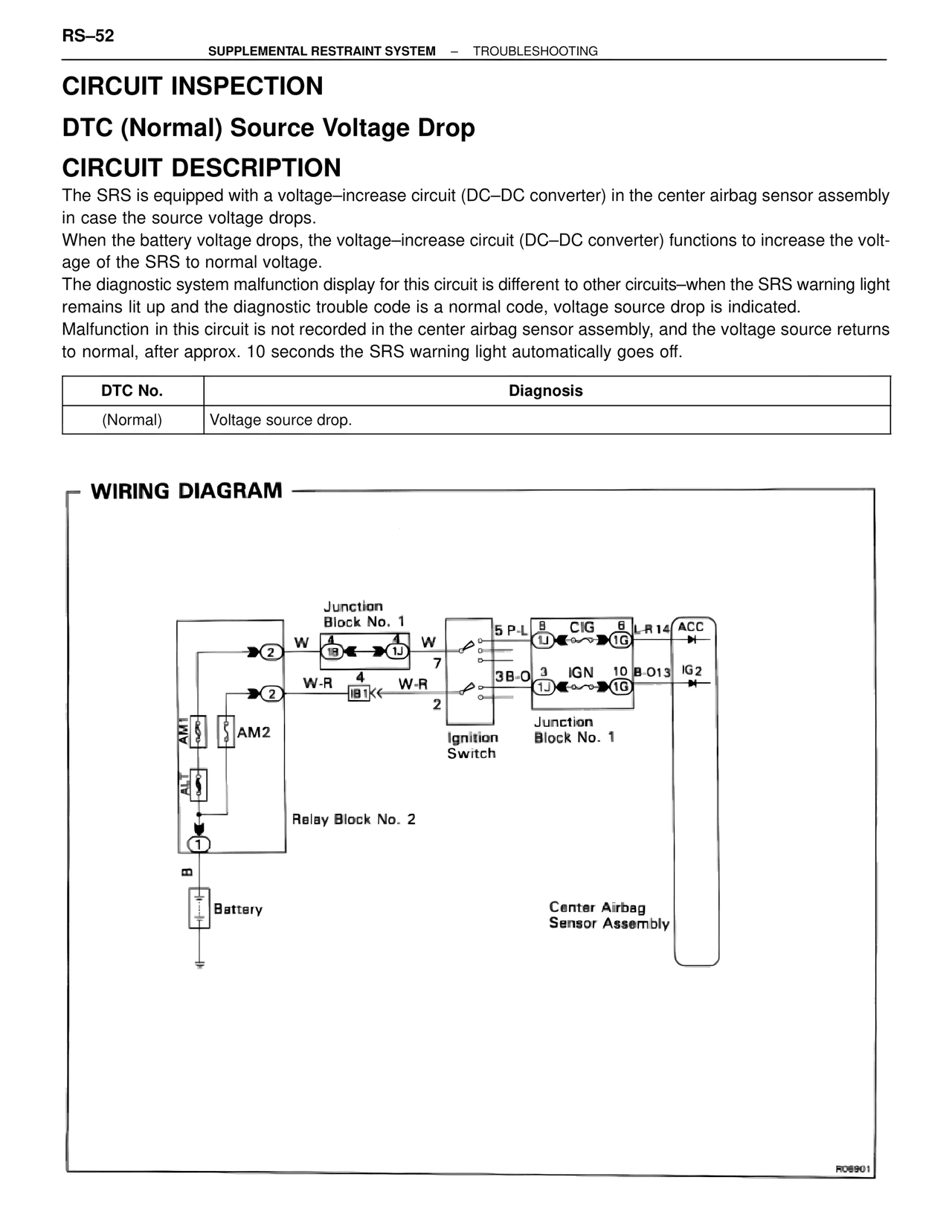
100%
Page text (OCR transcript)
RS–52
SUPPLEMENTAL RESTRAINT SYSTEM – TROUBLESHOOTING

CIRCUIT INSPECTION

DTC (Normal) Source Voltage Drop

CIRCUIT DESCRIPTION
The SRS is equipped with a voltage–increase circuit (DC–DC converter) in the center airbag sensor assembly in case the source voltage drops.
When the battery voltage drops, the voltage–increase circuit (DC–DC converter) functions to increase the voltage of the SRS to normal voltage.
The diagnostic system malfunction display for this circuit is different to other circuits–when the SRS warning light remains lit up and the diagnostic trouble code is a normal code, voltage source drop is indicated.
Malfunction in this circuit is not recorded in the center airbag sensor assembly, and the voltage source returns to normal, after approx. 10 seconds the SRS warning light automatically goes off.

DTC No.          Diagnosis
(Normal)          Voltage source drop.

WIRING DIAGRAM

Junction Block No. 1
W    4         4    W
1B        1J

W-R   4      W-R
1B1

AM1
AM2

Relay Block No. 2

Battery
B

5 P-L   8    CIG    6   L-R14   ACC
1J        1G

3B-O   3    IGN    10  B-O13   IG2
1J        1G

Ignition Switch

Junction Block No. 1

Center Airbag Sensor Assembly

R06901