Page text (OCR transcript)
RS–59
SUPPLEMENTAL RESTRAINT SYSTEM – TROUBLESHOOTING

From the results of the above inspection, the malfunctioning part can now be considered normal.
To make sure of this, use the simulation method to check. If the malfunctioning part cannot be
detected by the simulation method, replace all SRS components including the wire harness.

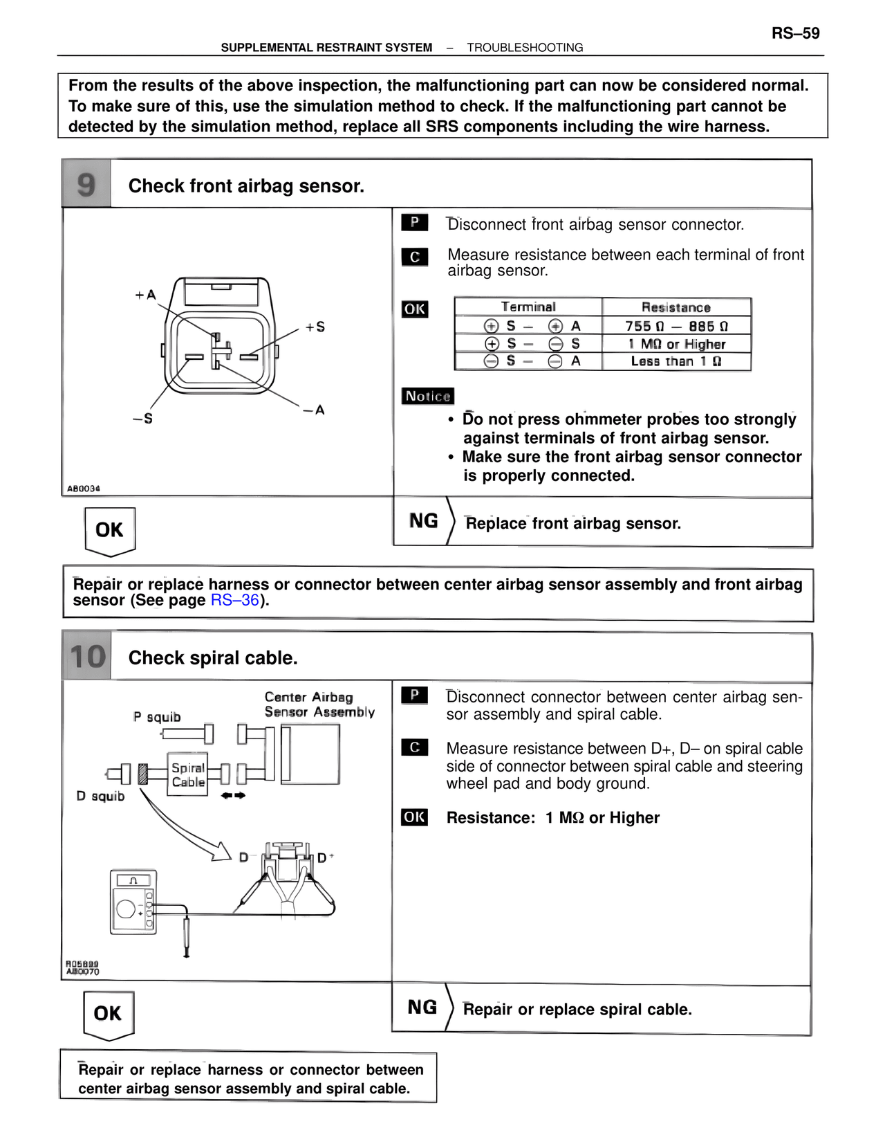
9  Check front airbag sensor.

P  Disconnect front airbag sensor connector.

C  Measure resistance between each terminal of front
airbag sensor.

OK
Terminal          Resistance
+ S – + A     755 Ω – 885 Ω
+ S – – S     1 MΩ or Higher
– S – – A     Less than 1 Ω

Notice
• Do not press ohmmeter probes too strongly
against terminals of front airbag sensor.
• Make sure the front airbag sensor connector
is properly connected.

+A
+S
–S
–A
AB0034

OK                    NG  Replace front airbag sensor.

Repair or replace harness or connector between center airbag sensor assembly and front airbag
sensor (See page RS–36).

10  Check spiral cable.

Center Airbag
Sensor Assembly
P squib
Spiral
Cable
D squib
D–    D+
R05899
AB0070

P  Disconnect connector between center airbag sen-
sor assembly and spiral cable.

C  Measure resistance between D+, D– on spiral cable
side of connector between spiral cable and steering
wheel pad and body ground.

OK  Resistance:  1 MΩ or Higher

OK                    NG  Repair or replace spiral cable.

Repair or replace harness or connector between
center airbag sensor assembly and spiral cable.