100%
RS–60
SUPPLEMENTAL RESTRAINT SYSTEM – TROUBLESHOOTING
DTC 12 Short in Squib Circuit (to B+)
CIRCUIT DESCRIPTION
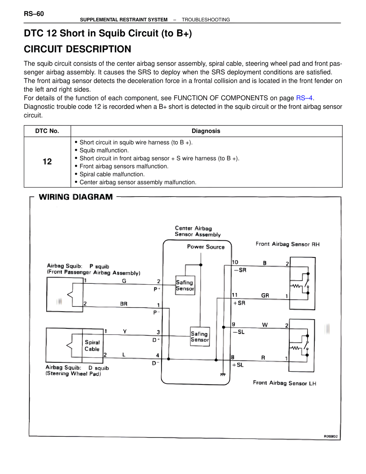
The squib circuit consists of the center airbag sensor assembly, spiral cable, steering wheel pad and front pas-
senger airbag assembly. It causes the SRS to deploy when the SRS deployment conditions are satisfied.
The front airbag sensor detects the deceleration force in a frontal collision and is located in the front fender on
the left and right sides.
For details of the function of each component, see FUNCTION OF COMPONENTS on page RS–4.
Diagnostic trouble code 12 is recorded when a B+ short is detected in the squib circuit or the front airbag sensor
circuit.
DTC No. | Diagnosis
12
• Short circuit in squib wire harness (to B +).
• Squib malfunction.
• Short circuit in front airbag sensor + S wire harness (to B +).
• Front airbag sensors malfunction.
• Spiral cable malfunction.
• Center airbag sensor assembly malfunction.
WIRING DIAGRAM
Center Airbag
Sensor Assembly
Power Source
Front Airbag Sensor RH
Airbag Squib: P squib
(Front Passenger Airbag Assembly)
1 G 2
P+
2 BR 1
P-
10 B 2
-SR
Safing
Sensor
11 GR 1
+SR
1 Y 3
D+
Spiral
Cable
2 L 4
D-
Safing
Sensor
9 W 2
-SL
8 R 1
+SL
Airbag Squib: D squib
(Steering Wheel Pad)
Front Airbag Sensor LH
R06802