100%
RS–61
SUPPLEMENTAL RESTRAINT SYSTEM – TROUBLESHOOTING
INSPECTION PROCEDURES
[P] Preparation [C] Check
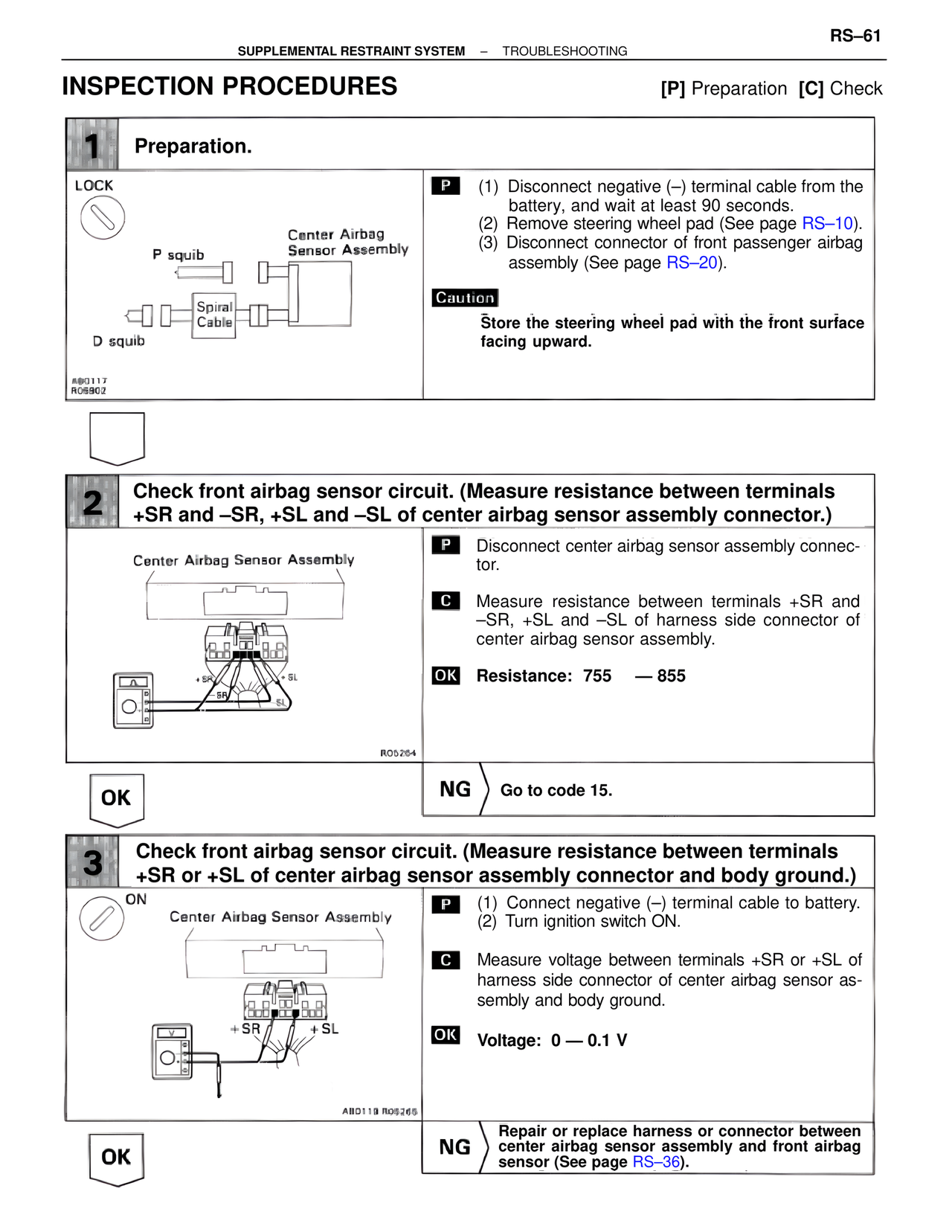
1 Preparation.
LOCK
P squib
Center Airbag
Sensor Assembly
Spiral
Cable
D squib
AB0117
RO5902
P (1) Disconnect negative (–) terminal cable from the
battery, and wait at least 90 seconds.
(2) Remove steering wheel pad (See page RS–10).
(3) Disconnect connector of front passenger airbag
assembly (See page RS–20).
Caution
Store the steering wheel pad with the front surface
facing upward.
2 Check front airbag sensor circuit. (Measure resistance between terminals
+SR and –SR, +SL and –SL of center airbag sensor assembly connector.)
Center Airbag Sensor Assembly
+SR
SR
+SL
SL
RO5264
P Disconnect center airbag sensor assembly connector.
C Measure resistance between terminals +SR and
–SR, +SL and –SL of harness side connector of
center airbag sensor assembly.
OK Resistance: 755 — 855
OK
NG Go to code 15.
3 Check front airbag sensor circuit. (Measure resistance between terminals
+SR or +SL of center airbag sensor assembly connector and body ground.)
ON
Center Airbag Sensor Assembly
+SR +SL
AB0119 RO5265
P (1) Connect negative (–) terminal cable to battery.
(2) Turn ignition switch ON.
C Measure voltage between terminals +SR or +SL of
harness side connector of center airbag sensor as-
sembly and body ground.
OK Voltage: 0 — 0.1 V
OK
NG Repair or replace harness or connector between
center airbag sensor assembly and front airbag
sensor (See page RS–36).