100%
EG–427
ENGINE – 2JZ–GE ENGINE TROUBLESHOOTING
INSPECTION PROCEDURE
HINT: If diagnostic trouble codes "22" (engine coolant temperature sensor circuit), "24" (intake air temperature
sensor circuit) and "41" (throttle position sensor circuit) are output simultaneously, E2 (sensor ground)
may be open.
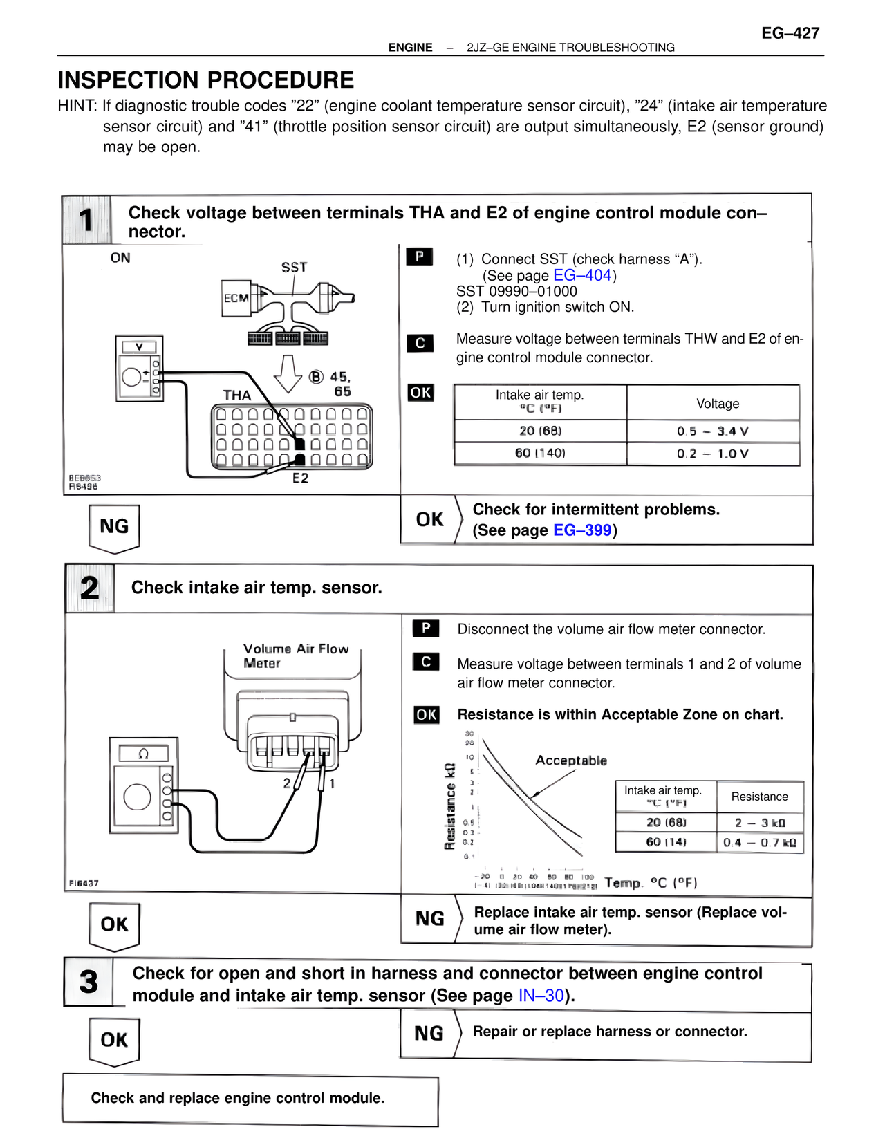
1 Check voltage between terminals THA and E2 of engine control module con–
nector.
ON
SST
ECM
(B) 45,
65
THA
BE6653
FI6496
E2
P (1) Connect SST (check harness "A").
(See page EG–404)
SST 09990–01000
(2) Turn ignition switch ON.
C Measure voltage between terminals THW and E2 of en-
gine control module connector.
OK
Intake air temp.
°C (°F) Voltage
20 (68) 0.5 – 3.4 V
60 (140) 0.2 – 1.0 V
NG
OK Check for intermittent problems.
(See page EG–399)
2 Check intake air temp. sensor.
Volume Air Flow
Meter
2 1
FI6437
P Disconnect the volume air flow meter connector.
C Measure voltage between terminals 1 and 2 of volume
air flow meter connector.
OK Resistance is within Acceptable Zone on chart.
Resistance kΩ
30
20
10
6
3
2
1
0.6
0.5
0.3
0.2
0.1
Acceptable
Intake air temp.
°C (°F) Resistance
20 (68) 2 – 3 kΩ
60 (14) 0.4 – 0.7 kΩ
-20 0 30 40 80 80 100
(-4) (32)(68)(104)(140)(176)(212) Temp. °C (°F)
OK
NG Replace intake air temp. sensor (Replace vol-
ume air flow meter).
3 Check for open and short in harness and connector between engine control
module and intake air temp. sensor (See page IN–30).
OK
NG Repair or replace harness or connector.
Check and replace engine control module.