100%
CIRCUIT INSPECTION
DTC 12 G NE Signal Circuit (No.1)
CIRCUIT DESCRIPTION
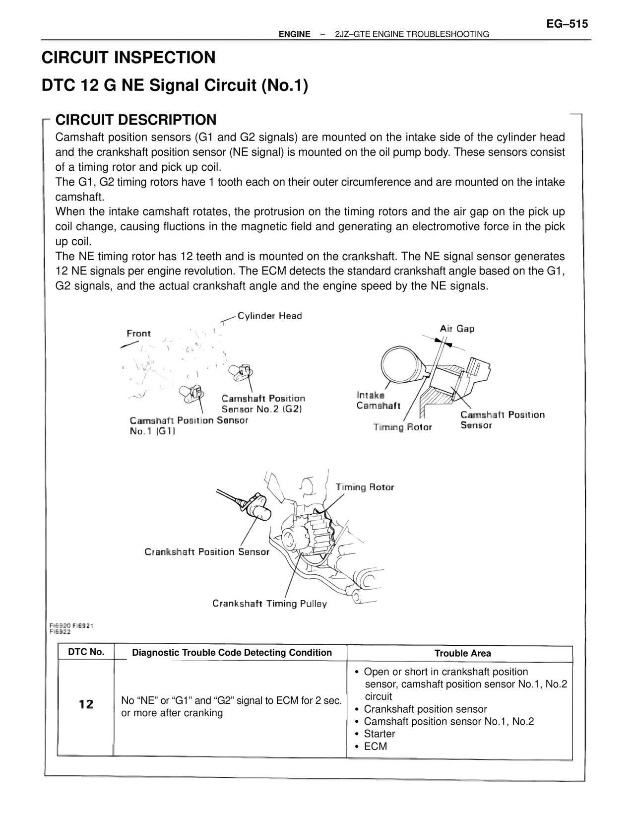
Camshaft position sensors (G1 and G2 signals) are mounted on the intake side of the cylinder head
and the crankshaft position sensor (NE signal) is mounted on the oil pump body. These sensors consist
of a timing rotor and pick up coil.
The G1, G2 timing rotors have 1 tooth each on their outer circumference and are mounted on the intake
camshaft.
When the intake camshaft rotates, the protrusion on the timing rotors and the air gap on the pick up
coil change, causing fluctions in the magnetic field and generating an electromotive force in the pick
up coil.
The NE timing rotor has 12 teeth and is mounted on the crankshaft. The NE signal sensor generates
12 NE signals per engine revolution. The ECM detects the standard crankshaft angle based on the G1,
G2 signals, and the actual crankshaft angle and the engine speed by the NE signals.
Cylinder Head
Front
Air Gap
Camshaft Position
Sensor No.2 (G2)
Intake
Camshaft
Camshaft Position Sensor
No.1 (G1)
Camshaft Position
Sensor
Timing Rotor
Timing Rotor
Crankshaft Position Sensor
Crankshaft Timing Pulley
FI6920 FI6921
FI6922
DTC No. | Diagnostic Trouble Code Detecting Condition | Trouble Area
12 | No "NE" or "G1" and "G2" signal to ECM for 2 sec.
or more after cranking | • Open or short in crankshaft position
sensor, camshaft position sensor No.1, No.2
circuit
• Crankshaft position sensor
• Camshaft position sensor No.1, No.2
• Starter
• ECM