100%
INSPECTION PROCEDURE
HINT: If diagnostic trouble codes "22" (engine coolant temperature sensor circuit), "24" (intake air temperature sensor circuit) and "41" (throttle position sensor circuit) are output simultaneously, E2 (sensor ground) may be open.
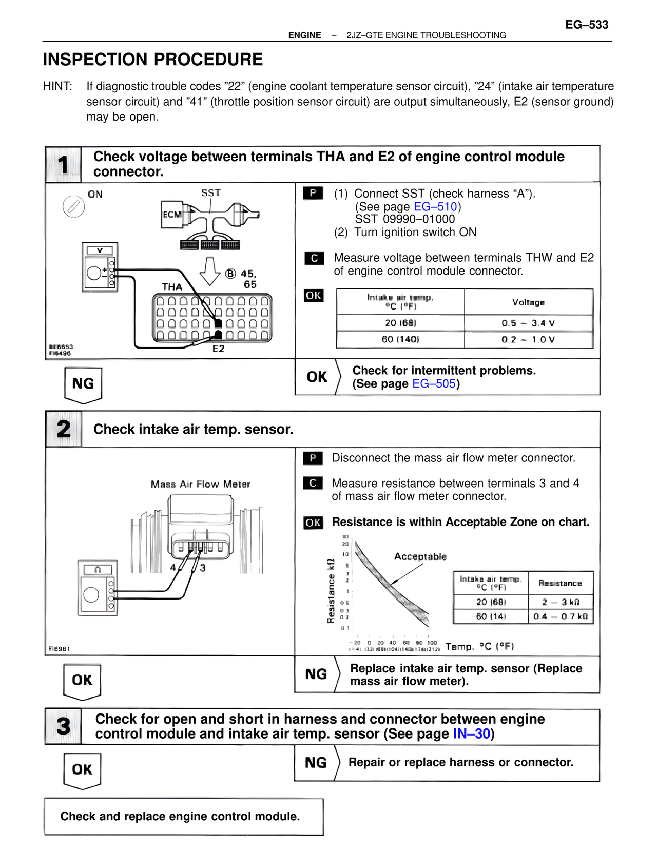
1 Check voltage between terminals THA and E2 of engine control module connector.
ON
SST
ECM
V
THA
B 45,
65
BE6653
FI6496
E2
P (1) Connect SST (check harness "A").
(See page EG-510)
SST 09990-01000
(2) Turn ignition switch ON
C Measure voltage between terminals THW and E2 of engine control module connector.
OK
Intake air temp.
°C (°F) | Voltage
20 (68) | 0.5 - 3.4 V
60 (140) | 0.2 - 1.0 V
NG
OK Check for intermittent problems.
(See page EG-505)
2 Check intake air temp. sensor.
Mass Air Flow Meter
4 3
FI6961
P Disconnect the mass air flow meter connector.
C Measure resistance between terminals 3 and 4 of mass air flow meter connector.
OK Resistance is within Acceptable Zone on chart.
Resistance kΩ
30
20
10
5
2
1
0.6
0.3
0.2
0.1
Acceptable
Intake air temp.
°C (°F) | Resistance
20 (68) | 2 - 3 kΩ
60 (14) | 0.4 - 0.7 kΩ
-20 0 20 40 60 80 100
(-4) (32)(68)(104)(140)(176)(212) Temp. °C (°F)
OK
NG Replace intake air temp. sensor (Replace mass air flow meter).
3 Check for open and short in harness and connector between engine control module and intake air temp. sensor (See page IN-30)
OK
NG Repair or replace harness or connector.
Check and replace engine control module.