Page text (OCR transcript)
EG–568

ENGINE – 2JZ–GTE ENGINE TROUBLESHOOTING

DTC 78 Fuel Pump Control Circuit

CIRCUIT DESCRIPTION
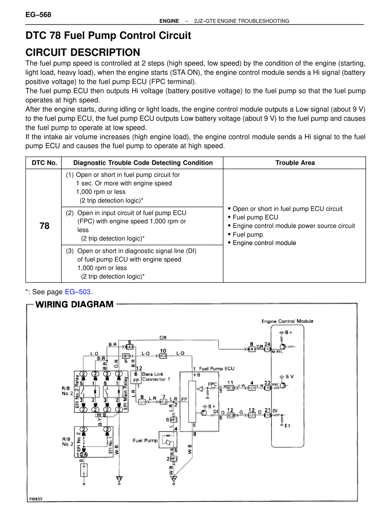
The fuel pump speed is controlled at 2 steps (high speed, low speed) by the condition of the engine (starting, light load, heavy load), when the engine starts (STA ON), the engine control module sends a Hi signal (battery positive voltage) to the fuel pump ECU (FPC terminal).
The fuel pump ECU then outputs Hi voltage (battery positive voltage) to the fuel pump so that the fuel pump operates at high speed.
After the engine starts, during idling or light loads, the engine control module outputs a Low signal (about 9 V) to the fuel pump ECU, the fuel pump ECU outputs Low battery voltage (about 9 V) to the fuel pump and causes the fuel pump to operate at low speed.
If the intake air volume increases (high engine load), the engine control module sends a Hi signal to the fuel pump ECU and causes the fuel pump to operate at high speed.

DTC No. | Diagnostic Trouble Code Detecting Condition | Trouble Area

78
(1) Open or short in fuel pump circuit for
    1 sec. Or more with engine speed
    1,000 rpm or less
    (2 trip detection logic)*
(2) Open in input circuit of fuel pump ECU
    (FPC) with engine speed 1,000 rpm or
    less
    (2 trip detection logic)*
(3) Open or short in diagnostic signal line (DI)
    of fuel pump ECU with engine speed
    1,000 rpm or less
    (2 trip detection logic)*

• Open or short in fuel pump ECU circuit
• Fuel pump ECU
• Engine control module power source circuit
• Fuel pump
• Engine control module

*: See page EG–503.

WIRING DIAGRAM

Engine Control Module

B+

GR
B-R    5
        EA3
L-O         L-O    10        L-O         8  GR  24
B-R                  IC2                EA1  E10    M-REL
G-R    4
        AR
        12
B              1  Fuel Pump ECU
FP    Data Link
      Connector 1    +B
L-R                        FPC    11        4  V-W  22  FPC
J1K         7  L-R  FP         IC3K    J1    E10
            J1K     2
                              +B+
B-R    7                    DI    12  G    12  G    21  DI
EFI No.2 Relay              6  BP         IC3K    J1    E10
                    E
EFI Main Relay    L     4         8
                              W-B
R/B                    Fuel Pump
No.2        W-B
                    2    W-B
EFI No.2                5
EFI No.1    W-B             W-B

R/B
No.2

FI6833