100%
INSPECTION PROCEDURE
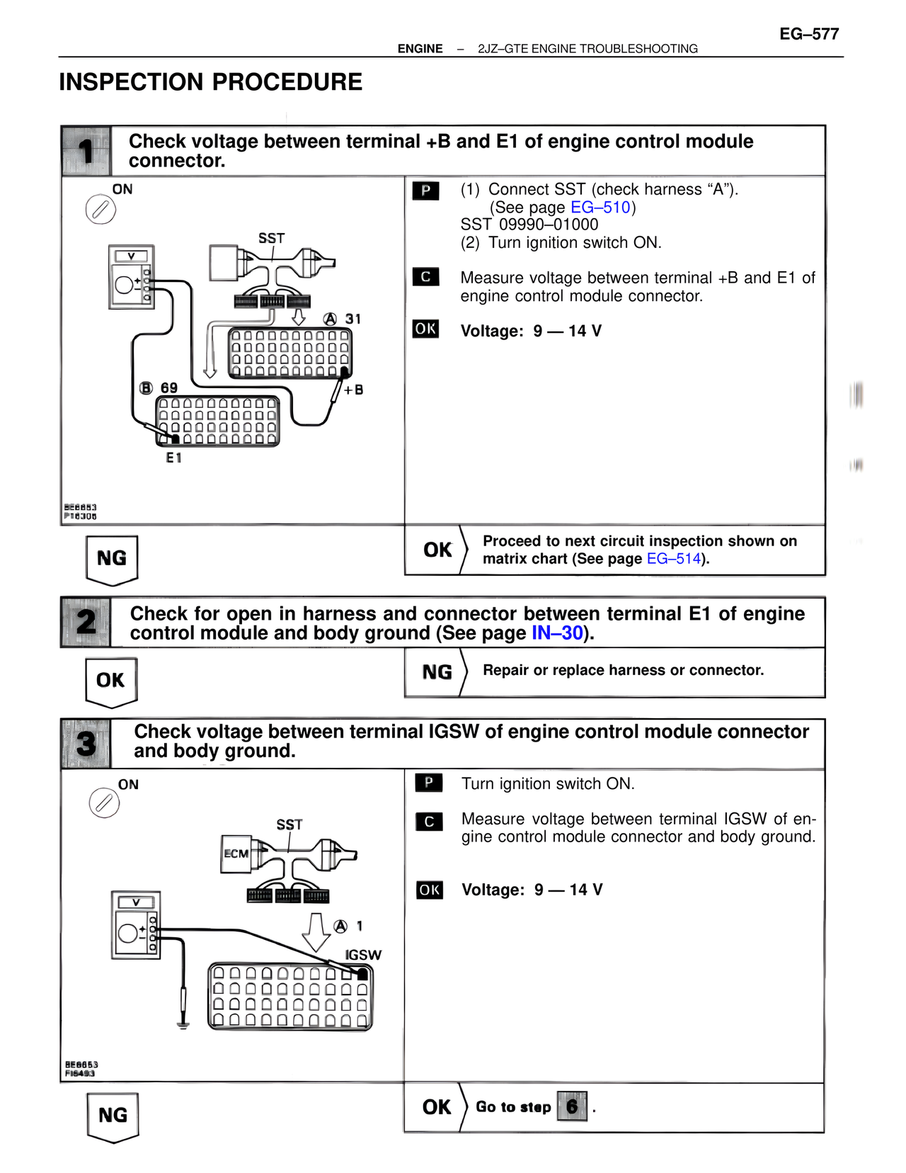
1 Check voltage between terminal +B and E1 of engine control module connector.
ON
SST
A 31
B 69
+B
E1
BE6853
P16306
P (1) Connect SST (check harness "A").
(See page EG–510)
SST 09990–01000
(2) Turn ignition switch ON.
C Measure voltage between terminal +B and E1 of engine control module connector.
OK Voltage: 9 — 14 V
NG
OK Proceed to next circuit inspection shown on matrix chart (See page EG–514).
2 Check for open in harness and connector between terminal E1 of engine control module and body ground (See page IN–30).
OK
NG Repair or replace harness or connector.
3 Check voltage between terminal IGSW of engine control module connector and body ground.
ON
SST
ECM
A 1
IGSW
BE6853
FI6493
P Turn ignition switch ON.
C Measure voltage between terminal IGSW of engine control module connector and body ground.
OK Voltage: 9 — 14 V
NG
OK Go to step 6 .