Page text (OCR transcript)
EG–582
ENGINE – 2JZ–GTE ENGINE TROUBLESHOOTING

INSPECTION PROCEDURE

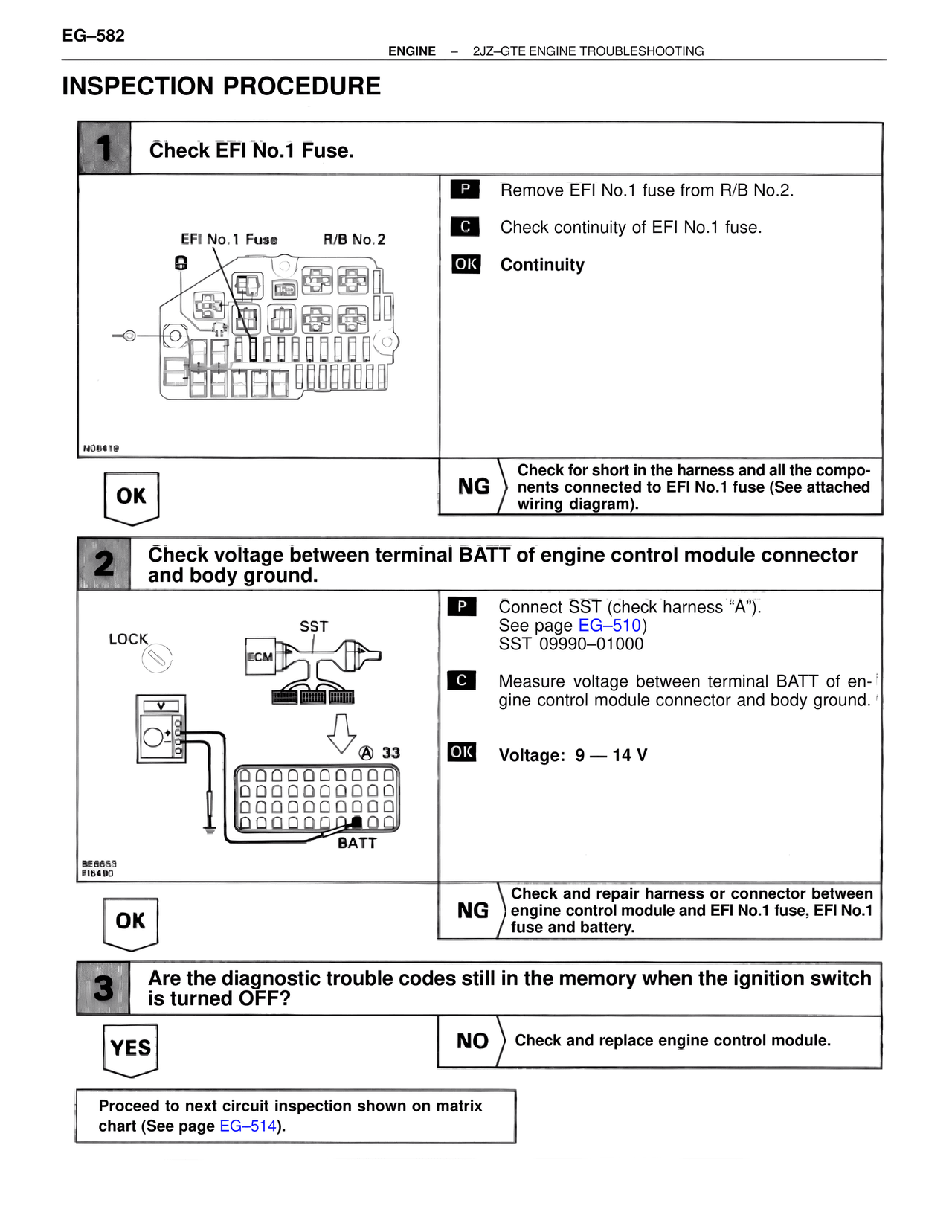
1 Check EFI No.1 Fuse.

EFI No.1 Fuse    R/B No.2

N08419

P  Remove EFI No.1 fuse from R/B No.2.

C  Check continuity of EFI No.1 fuse.

OK  Continuity

OK

NG  Check for short in the harness and all the components connected to EFI No.1 fuse (See attached wiring diagram).

2 Check voltage between terminal BATT of engine control module connector and body ground.

LOCK
SST
ECM

A 33

BATT

BE6653
FI6490

P  Connect SST (check harness "A").
See page EG–510)
SST 09990–01000

C  Measure voltage between terminal BATT of engine control module connector and body ground.

OK  Voltage: 9 — 14 V

OK

NG  Check and repair harness or connector between engine control module and EFI No.1 fuse, EFI No.1 fuse and battery.

3 Are the diagnostic trouble codes still in the memory when the ignition switch is turned OFF?

YES

NO  Check and replace engine control module.

Proceed to next circuit inspection shown on matrix chart (See page EG–514).