100%
Injector Circuit
CIRCUIT DESCRIPTION
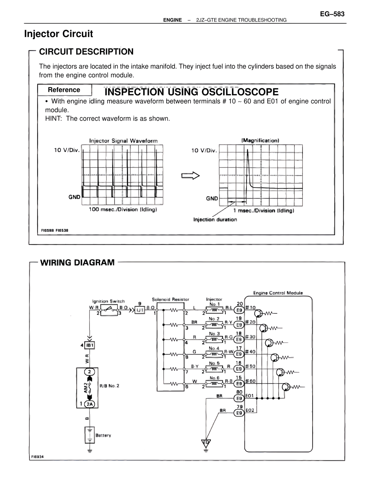
The injectors are located in the intake manifold. They inject fuel into the cylinders based on the signals from the engine control module.
Reference INSPECTION USING OSCILLOSCOPE
• With engine idling measure waveform between terminals # 10 ~ 60 and E01 of engine control module.
HINT: The correct waveform is as shown.
Injector Signal Waveform
10 V/Div.
GND
100 msec./Division (Idling)
(Magnification)
10 V/Div.
GND
1 msec./Division (Idling)
Injection duration
FI6598 FI6538
WIRING DIAGRAM
Ignition Switch
W-R
2
3
B-O
IJ1 B-O
9
1
Solenoid Resistor
L
2
Injector
No.1
R-L
E9
1
Engine Control Module
20
#10
BR
3
No.2
R-Y
E9
2
1
19
#20
R
4
No.3
R-G
E9
2
1
18
#30
G
8
No.4
R-W
E9
2
1
17
#40
B-Y
7
No.5
R
E9
2
1
16
#50
W
6
No.6
R-B
E9
2
1
15
#60
BR
E9
80
EO1
BR
E9
79
EO2
4 IB1
W-R
2
AM2
R/B No.2
1
2A
B
Battery
FI6934