Page text (OCR transcript)
Q : Explains the system outline.

R : Indicates values or explains the function for reference during troubleshooting.

S : Indicates the reference page showing the position on the vehicle of the parts in the system circuit.
    Example: Part "P4" (Power Window Master SW) is on page 21 of the manual.
        *  The letter in the code is from the first letter of the part, and the number indicates its order
           in parts starting with that letter.
           Example: P 4
                        |_____ Part is 4th in order
                   |__________ Power Window Master SW

T : Indicates the reference page showing the position on the vehicle of Relay Block Connectors in the
    system circuit.
    Example: Connector "1" is described on page 16 of this manual and is installed on the left side of the
             instrument panel.

U : Indicates the reference page showing the position on the vehicle of J/B and Wire Harness in the system
    circuit.
    Example: Connector "3B"connects the Cowl Wire and J/B No. 3. It is described on page 14 of this
             manual, and is installed on the instrument panel left side.

V : Indicates the reference page describing the wiring harness and wiring harness connector (the female
    wiring harness is shown first, followed by the male wiring harness).
    Example: Connector "ID1"connects the front door RH wire (female) and cowl wire (male). It is described
             on page 26 of this manual, and is installed on the right side kick panel.

W : Indicates the reference page showing the position of the ground points on the vehicle.
    Example: Ground point "IC" is described on page 24 of this manual and is installed on the cowl left side.

X : Indicates the reference page showing the position of the splice points on the vehicle.
    Example: Splice point "I 5" is on the Cowl Wire Harness and is described on page 24 of this manual.

HINT:
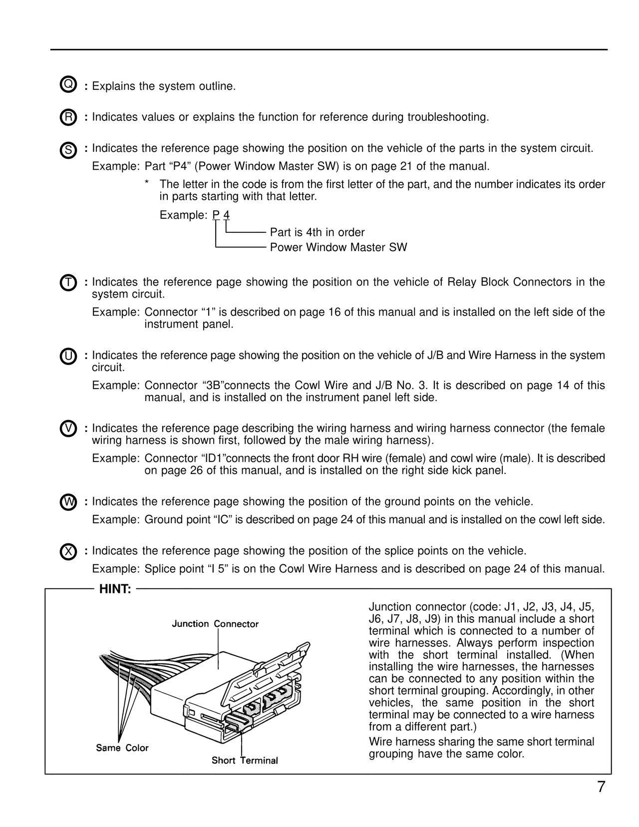
Junction Connector
Same Color
Short Terminal

Junction connector (code: J1, J2, J3, J4, J5,
J6, J7, J8, J9) in this manual include a short
terminal which is connected to a number of
wire harnesses. Always perform inspection
with the short terminal installed. (When
installing the wire harnesses, the harnesses
can be connected to any position within the
short terminal grouping. Accordingly, in other
vehicles, the same position in the short
terminal may be connected to a wire harness
from a different part.)
Wire harness sharing the same short terminal
grouping have the same color.

7