100%
HOW TO USE THIS MANUAL
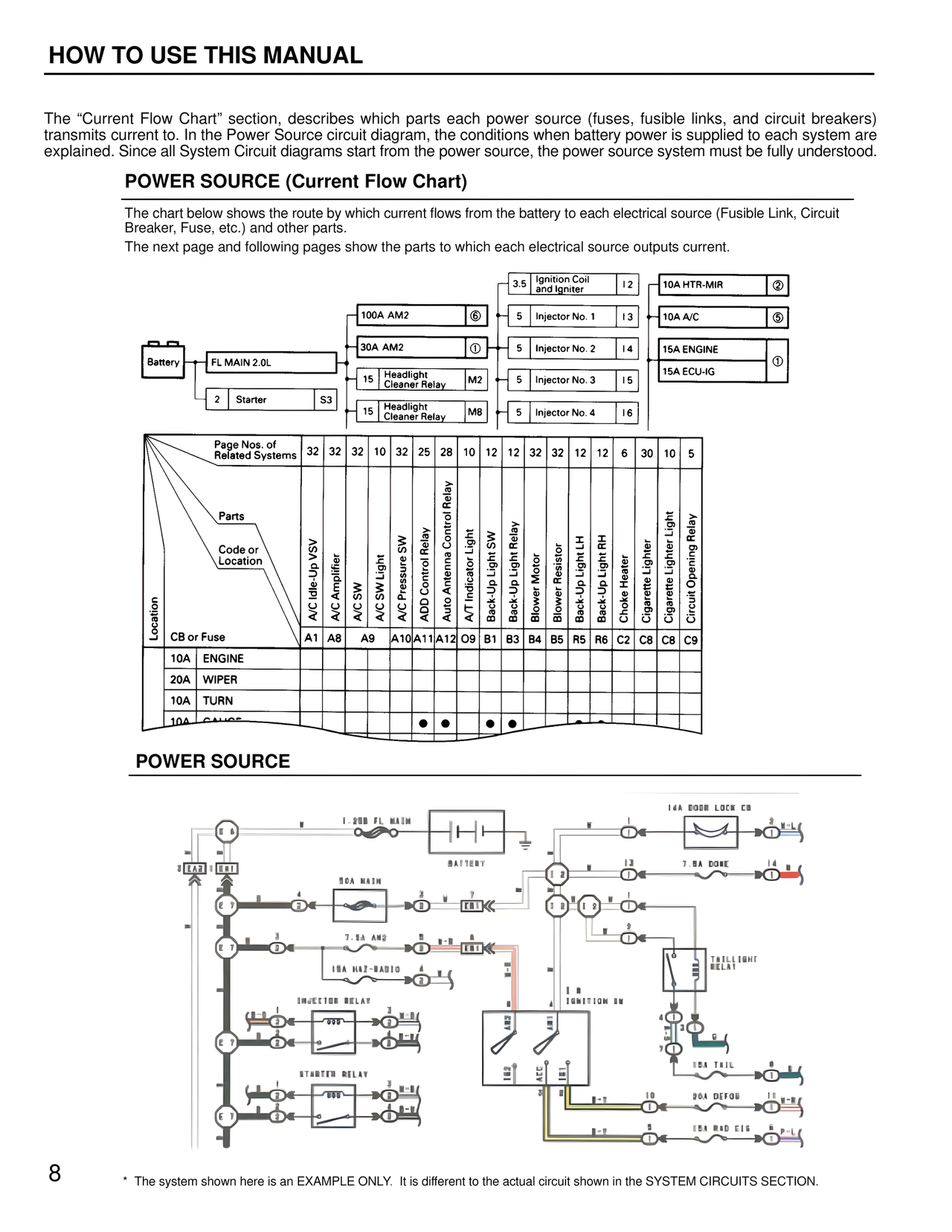
The "Current Flow Chart" section, describes which parts each power source (fuses, fusible links, and circuit breakers) transmits current to. In the Power Source circuit diagram, the conditions when battery power is supplied to each system are explained. Since all System Circuit diagrams start from the power source, the power source system must be fully understood.
POWER SOURCE (Current Flow Chart)
The chart below shows the route by which current flows from the battery to each electrical source (Fusible Link, Circuit Breaker, Fuse, etc.) and other parts.
The next page and following pages show the parts to which each electrical source outputs current.
3.5 Ignition Coil and Igniter I2
10A HTR-MIR 2
100A AM2 6
5 Injector No. 1 I3
10A A/C 5
30A AM2 1
5 Injector No. 2 I4
15A ENGINE
FL MAIN 2.0L
15 Headlight Cleaner Relay M2
5 Injector No. 3 I5
15A ECU-IG 1
Battery
15 Headlight Cleaner Relay M8
5 Injector No. 4 I6
2 Starter S3
Page Nos. of Related Systems 32 32 32 10 32 25 28 10 12 12 32 32 12 12 6 30 10 5
Parts
Code or Location
Location
CB or Fuse
A/C Idle-Up VSV A1
A/C Amplifier A8
A/C SW A9
A/C SW Light A10
A/C Pressure SW A11
ADD Control Relay A12
Auto Antenna Control Relay O9
A/T Indicator Light B1
Back-Up Light SW B3
Back-Up Light Relay B4
Blower Motor B5
Blower Resistor R5
Back-Up Light LH R6
Back-Up Light RH C2
Choke Heater C8
Cigarette Lighter C8
Cigarette Lighter Light C9
Circuit Opening Relay
10A ENGINE
20A WIPER
10A TURN
10A GAUGE
POWER SOURCE
14A DOOR LOCK CB
1.25B FL MAIN
BATTERY
7.5A DOME
90A MAIN
7.5A AM2
15A HAZ-RADIO
INJECTOR RELAY
IGNITION SW
TAILLIGHT RELAY
STARTER RELAY
10A TAIL
30A DEFOG
15A RAD C/G
8
* The system shown here is an EXAMPLE ONLY. It is different to the actual circuit shown in the SYSTEM CIRCUITS SECTION.