100%
A–5
INTRODUCTION–HOW TO PERFORM FOR SYSTEM INSPECTION
HOW TO PERFORM FOR SYSTEM INSPECTION
This inspection procedure is a simple troubleshooting which should be carried out on the vehicle during system operation and is based on the assumption of system component trouble
Always inspect the trouble taking the following items into consideration:
● Ground point fault
● Open or short circuit of the wire harness
● Connector or terminal connection fault
● Fuse or fusible link fault
NOTICE:
● This is an on–vehicle inspection during system operation.
Therefore, inspect the trouble with due regard for safety.
● If connecting the battery directly, be careful not to cause a short circuit, and select the applicable voltage.
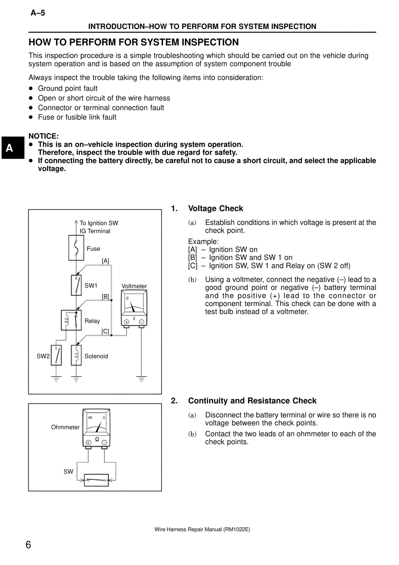
To Ignition SW
IG Terminal
Fuse
[A]
SW1
Voltmeter
[B]
Relay
[C]
SW2
Solenoid
1. Voltage Check
(a) Establish conditions in which voltage is present at the check point.
Example:
[A] – Ignition SW on
[B] – Ignition SW and SW 1 on
[C] – Ignition SW, SW 1 and Relay on (SW 2 off)
(b) Using a voltmeter, connect the negative (–) lead to a good ground point or negative (–) battery terminal and the positive (+) lead to the connector or component terminal. This check can be done with a test bulb instead of a voltmeter.
Ohmmeter
SW
2. Continuity and Resistance Check
(a) Disconnect the battery terminal or wire so there is no voltage between the check points.
(b) Contact the two leads of an ohmmeter to each of the check points.
Wire Harness Repair Manual (RM1022E)
6