2. INSTALL REAR SUPPORT MEMBER
(a) Install the support member to the chassis and lower the transmission to allow installation of the center bolts.
(b) Install the ground strap and rubber exhaust hanger.
3. INSTALL PROPELLER SHAFT
4. INSTALL SPEED SENSOR
5. INSTALL SPEEDOMETER DRIVEN GEAR
(a) Install a new O-ring on the shaft sleeve.
(b) Install the lock plate with a bolt and washer.
6. CONNECT SPEEDOMETER CABLE
Place the felt dust protector and washer on the end of the cable. Tighten the collar with pliers.
7. LOWER VEHICLE AND CHECK FLUID LEVEL (See page MA-13)
Start the engine, shift the selector into each gear, then check the fluid level with the transmission in "P" range. Add fluid as necessary.
CAUTION: Do not overfill.
Fluid type: ATF DEXRON® II
REMOVAL OF ROTOR SENSOR
1. REMOVE EXTENSION HOUSING (See page AT-38)
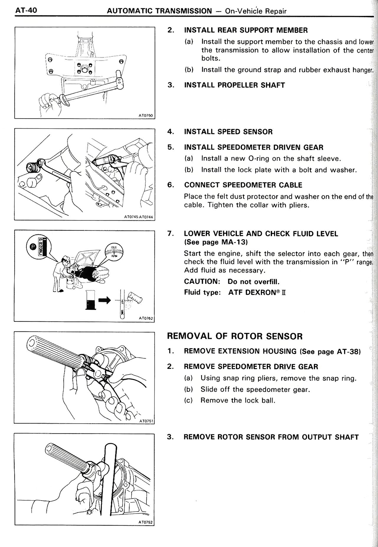
2. REMOVE SPEEDOMETER DRIVE GEAR
(a) Using snap ring pliers, remove the snap ring.
(b) Slide off the speedometer gear.
(c) Remove the lock ball.
3. REMOVE ROTOR SENSOR FROM OUTPUT SHAFT