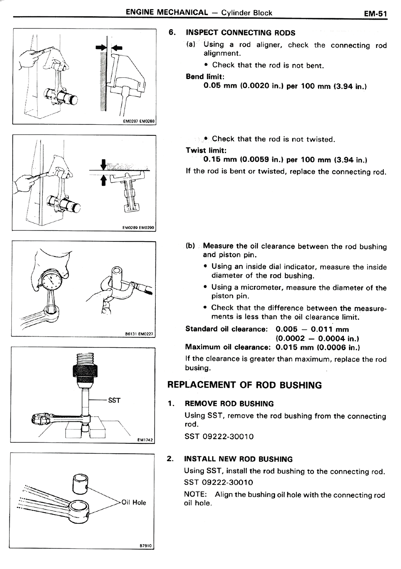
6. INSPECT CONNECTING RODS
(a) Using a rod aligner, check the connecting rod alignment.
• Check that the rod is not bent.
Bend limit:
0.05 mm (0.0020 in.) per 100 mm (3.94 in.)
• Check that the rod is not twisted.
Twist limit:
0.15 mm (0.0059 in.) per 100 mm (3.94 in.)
If the rod is bent or twisted, replace the connecting rod.
(b) Measure the oil clearance between the rod bushing and piston pin.
• Using an inside dial indicator, measure the inside diameter of the rod bushing.
• Using a micrometer, measure the diameter of the piston pin.
• Check that the difference between the measurements is less than the oil clearance limit.
Standard oil clearance: 0.005 — 0.011 mm
(0.0002 — 0.0004 in.)
Maximum oil clearance: 0.015 mm (0.0006 in.)
If the clearance is greater than maximum, replace the rod bushing.
REPLACEMENT OF ROD BUSHING
1. REMOVE ROD BUSHING
Using SST, remove the rod bushing from the connecting rod.
SST 09222-30010
2. INSTALL NEW ROD BUSHING
Using SST, install the rod bushing to the connecting rod.
SST 09222-30010
NOTE: Align the bushing oil hole with the connecting rod oil hole.