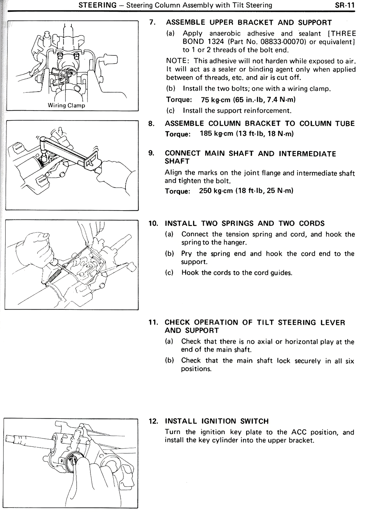
7. ASSEMBLE UPPER BRACKET AND SUPPORT
(a) Apply anaerobic adhesive and sealant (THREE BOND 1324 (Part No. 08833-00070) or equivalent) to 1 or 2 threads of the bolt end.
NOTE: This adhesive will not harden while exposed to air. It will act as a sealer or binding agent only when applied between of threads, etc. and air is cut off.
(b) Install the two bolts; one with a wiring clamp.
Torque: 75 kg-cm (65 in.-lb, 7.4 N-m)
AcI Install the support reinforcement.
8. ASSEMBLE COLUMN BRACKET TO COLUMN TUBE
Torque: 185 kg-cm (13 ft-lb, 18 N-m)
9. CONNECT MAIN SHAFT AND INTERMEDIATE SHAFT
Align the marks on the joint flange and intermediate shaft and tighten the bolt.
Torque: 250 kg-cm (18 ft-lb, 25 N-m)
10. INSTALL TWO SPRINGS AND TWO CORDS
(a) Connect the tension spring and cord, and hook the spring to the hanger.
(b) Pry the spring end and hook the cord end to the support.
(c) Hook the cords to the cord guides.
11. CHECK OPERATION OF TILT STEERING LEVER AND SUPPORT
(a) Check that there is no axial or horizontal play at the end of the main shaft.
(b) Check that the main shaft lock securely in all six positions.
12. INSTALL IGNITION SWITCH
Turn the ignition key plate to the ACC position, and install the key cylinder into the upper bracket.