STEERING — Power Steering SR-37
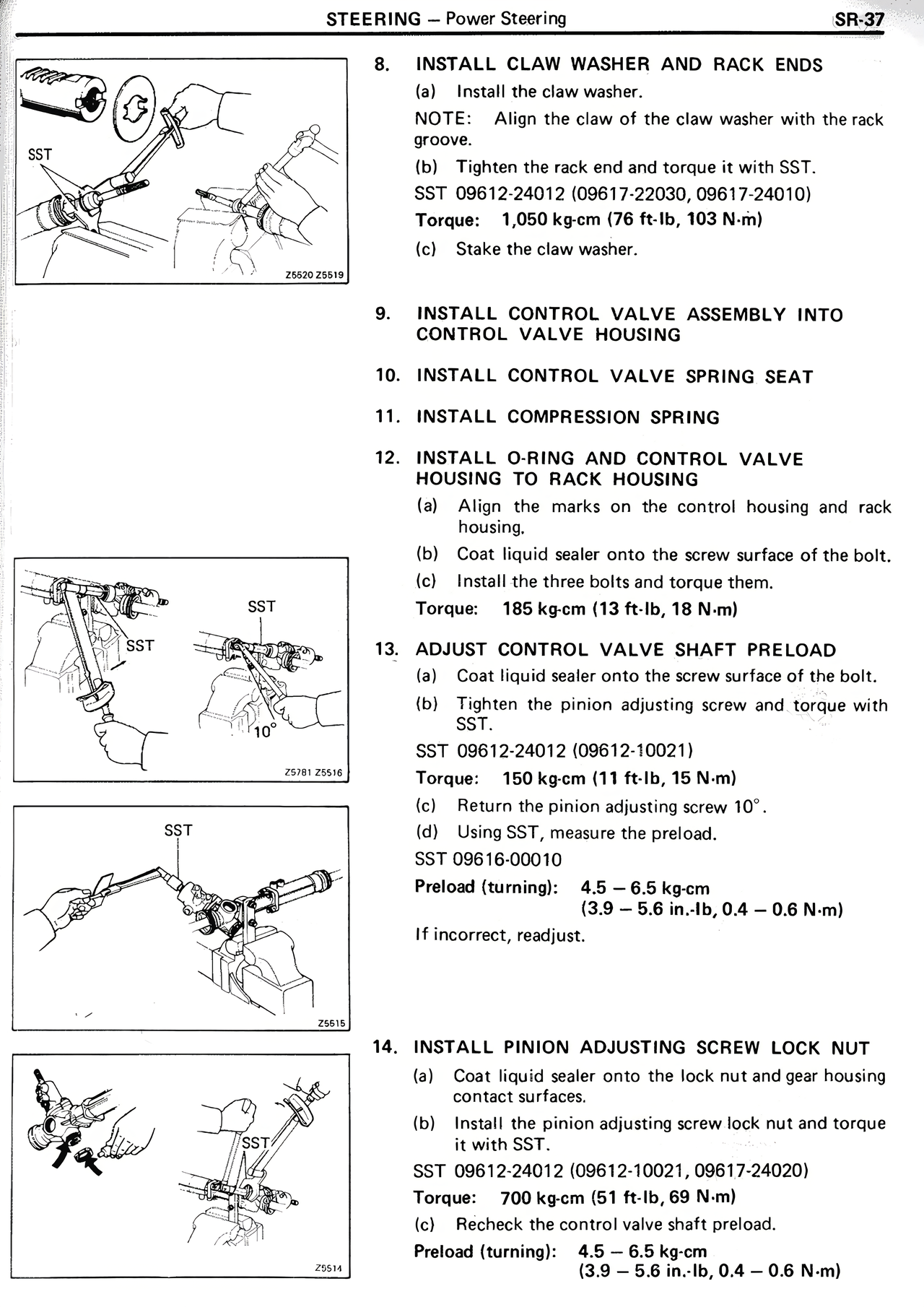
8. INSTALL CLAW WASHER AND RACK ENDS
(a) Install the claw washer.
NOTE: Align the claw of the claw washer with the rack groove.
(b) Tighten the rack end and torque it with SST.
SST 09612-24012 (09617-22030, 09617-24010)
Torque: 1,050 kg·cm (76 ft·lb, 103 N·m)
(c) Stake the claw washer.
9. INSTALL CONTROL VALVE ASSEMBLY INTO CONTROL VALVE HOUSING
10. INSTALL CONTROL VALVE SPRING SEAT
11. INSTALL COMPRESSION SPRING
12. INSTALL O-RING AND CONTROL VALVE SPRING TO RACK HOUSING
(a) Align the marks on the control housing and rack housing.
(b) Coat liquid sealer onto the screw surface of the bolt.
(c) Install the three bolts and torque them.
Torque: 185 kg·cm (13 ft·lb, 18 N·m)
13. ADJUST CONTROL VALVE SHAFT PRELOAD
(a) Coat liquid sealer onto the screw surface of the bolt.
(b) Tighten the pinion adjusting screw and torque with SST.
SST (09612-24012 (09612-10021)
Torque: 150 kg·cm (11 ft·lb, 15 N·m)
(c) Return the pinion adjusting screw 10°.
(d) Using SST, measure the preload.
SST 09616-00010
Preload (turning): 4.5 — 6.5 kg·cm
(3.9 — 5.6 in.·lb, 0.4 — 0.6 N·m)
If incorrect, readjust.
14. INSTALL PINION ADJUSTING SCREW LOCK NUT
(a) Coat liquid sealer onto the lock nut and gear housing contact surfaces.
(b) Install the pinion adjusting screw lock nut and torque it with SST.
SST 09612-24012 (09612-10021, 09617-24020)
Torque: 700 kg·cm (51 ft·lb, 69 N·m)
(c) Recheck the control valve shaft preload.
Preload (turning): 4.5 — 6.5 kg·cm
(3.9 — 5.6 in.·lb, 0.4 — 0.6 N·m)