100%
BE-18 BODY ELECTRICAL SYSTEM — Lighting
(b) Check that there is no continuity between terminals
with the rheostat turned off.
If operation is not as specified, replace the rheostat.
[DIAGRAM: Shows OFF position rheostat with multimeter showing "No continuity"]
Light Control Rheostat (Digital Type)
INSPECTION OF LIGHT CONTROL RHEOSTAT
INSPECT RHEOSTAT OPERATION
Connect the positive (+) lead from the battery to terminal
1. Connect the negative (—) lead to terminal 4.
(a) With the brightness at minimum, check that there is
9V between terminals 1 and 3.
(b) Gradually turn the rheostat toward the brighter side
and check that the voltage between terminals 1 and 3
decreases from 9V to 0V.
(c) With the brightness at minimum, check that there is
0V between terminals 2 and 4 and 12V when brightness is at any other level.
If operation is not as specified, replace the rheostat.
[DIAGRAMS: Two technical drawings showing rheostat testing configurations]
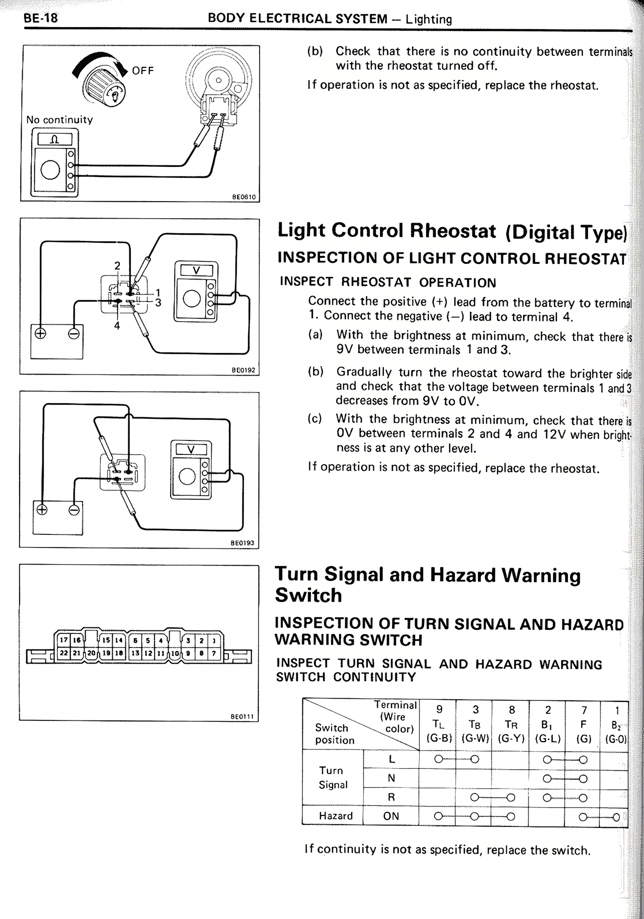
Turn Signal and Hazard Warning
Switch
INSPECTION OF TURN SIGNAL AND HAZARD
WARNING SWITCH
INSPECT TURN SIGNAL AND HAZARD WARNING
SWITCH CONTINUITY
[DIAGRAM: Connector terminal layout showing numbered positions]
Switch
position | Terminal
(Wire
Color) | 9
TL
(G-B) | 3
TB
(G-W) | 8
TR
(G-Y) | 2
B+
(G-L) | 7
F
(G) | 1
B2
(G-0)
Turn
Signal | L
M
R | O——O
O——O
O——O | O——O
O——O
O——O | O——O
O——O
O——O
Hazard | ON | O——O——O | | O——O
If continuity is not as specified, replace the switch.