100%
REPLACEMENT OF TURN SIGNAL AND HAZARD WARNING SWITCH
REPLACE TURN SIGNAL AND HAZARD WARNING SWITCH
(a) Remove the terminals from the connector.
(See page BE-2)
(b) Remove the turn signal and hazard switch.
(c) Install the turn signal and hazard switch.
(d) Connect the terminals to the connector.
(See pages BE-3 and 18)
Turn Signal Flasher
INSPECTION OF TURN SIGNAL FLASHER
INSPECT FLASHER OPERATION
(a) Connect the positive (+) lead from the battery to terminal 3. Connect the negative (—) lead to terminal 2 and R.
(b) Connect a 55W bulb between terminals 1 and 2, and check that the bulb goes on and off.
NOTE: The turn signal lights should flash 75 to 95 times per minute.
If one of the front or rear turn signal lights has an open circuit, the number of flashes will be more than 120 per minute.
If one of the side turn signal lights has an open circuit, the number of flashes will increase by about 10 per minute.
If operation is not as specified, replace the flasher.
Fade-Out Relay
INSPECTION OF FADE-OUT RELAY
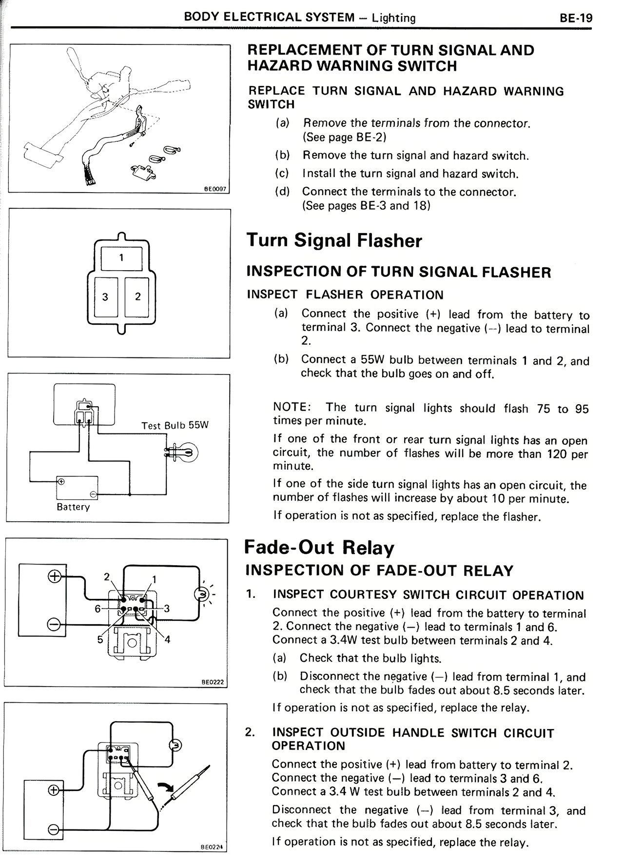
1. INSPECT COURTESY SWITCH CIRCUIT OPERATION
Connect the positive (+) lead from the battery to terminal 2. Connect the negative (—) lead to terminals 1 and 6.
Connect a 3.4W test bulb between terminals 2 and 4.
(a) Check that the bulb lights.
(b) Disconnect the negative (—) lead from terminal 1, and check that the bulb fades out about 8.5 seconds later.
If operation is not as specified, replace the relay.
2. INSPECT OUTSIDE HANDLE SWITCH CIRCUIT OPERATION
Connect the positive (+) lead from battery to terminal 2.
Connect the negative (—) lead to terminals 3 and 6.
Connect a 3.4 W test bulb between terminals 2 and 4.
Disconnect the negative (—) lead from terminal 3, and check that the bulb fades out about 8.5 seconds later.
If operation is not as specified, replace the relay.