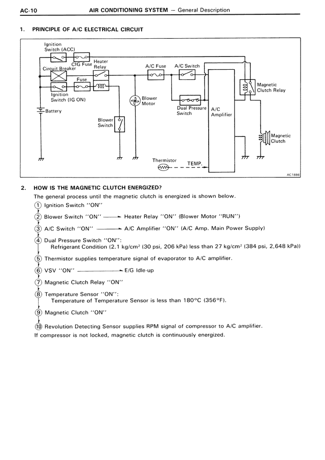
1. PRINCIPLE OF A/C ELECTRICAL CIRCUIT
[Diagram showing electrical circuit with components: Ignition Switch (ACC), Circuit Breaker, HTR Fuse, Fuse, Battery, Heater Motor, Blower Motor, Blower Switch, A/C Fuse, A/C Switch, Dual Pressure Switch, A/C Amplifier, Magnetic Clutch Relay, Magnetic Clutch, Thermistor, TEMP]
2. HOW IS THE MAGNETIC CLUTCH ENERGIZED?
The general process until the magnetic clutch is energized is shown below.
① Ignition Switch "ON"
|
② Blower Switch "ON" ——→ Heater Relay "ON" (Blower Motor "RUN")
|
③ A/C Switch "ON" ——→ A/C Amplifier "ON" (A/C Amp. Main Power Supply)
|
④ Dual Pressure Switch "ON":
Refrigerant Condition (2.1 kg/cm² (30 psi, 206 kPa) less than 27 kg/cm² (384 psi, 2,648 kPa))
|
⑤ Thermistor supplies temperature signal of evaporator to A/C amplifier.
|
⑥ VSV "ON" ——→ E/G Idle-up
|
⑦ Magnetic Clutch Relay "ON"
|
⑧ Temperature Sensor "ON":
Temperature of Temperature Sensor is less than 180°C (356°F).
|
⑨ Magnetic Clutch "ON"
|
⑩ Revolution Detecting Sensor supplies RPM signal of compressor to A/C amplifier.
If compressor is not locked, magnetic clutch is continuously energized.