AUTOMATIC TRANSMISSION — Installation of Component Parts AT-137
[Diagram showing Cam and Throttle Cable with reference AT3009]
(b) Connect the throttle cable to the cam.
(c) Confirm the springs into the accumulator pistons are installed correctly.
[Diagram showing bolt positions with measurements: 23 (0.91), 32 (1.26), 32 (1.26), 32 (1.26), 23 (0.91), 23 (0.91) mm, reference D4723]
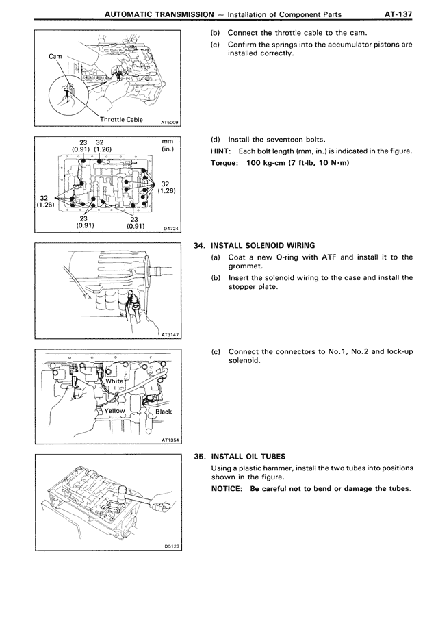
(d) Install the seventeen bolts.
HINT: Bolt length from, as indicated in the figure.
Torque: 100 kg-cm (7 ft-lb, 10 N·m)
[Diagram showing solenoid wiring installation, reference AT3147]
34. INSTALL SOLENOID WIRING
(a) Coat a new O-ring with ATF and install it to the grommet.
(b) Insert the solenoid wiring to the case and install the stopper plate.
[Diagram showing connector positions with White, Yellow, and Black connectors, reference AT3154]
(c) Connect the connectors to No.1, No.2 and lock-up solenoid.
[Diagram showing oil tube installation, reference D5123]
35. INSTALL OIL TUBES
Using a plastic hammer, install the two tubes into positions shown in the figure.
NOTICE: Be careful not to bend or damage the tubes.