Page text (OCR transcript)
BE-98
BODY ELECTRICAL SYSTEM — Theft Deterrent System

Theft Deterrent Computer

INSPECTION OF THEFT DETERRENT COMPUTER

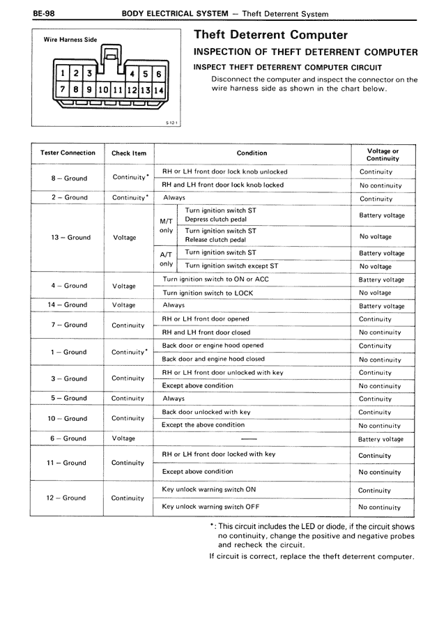
INSPECT THEFT DETERRENT COMPUTER CIRCUIT

Disconnect the computer and inspect the connector on the wire harness side as shown in the chart below.

Wire Harness Side
[Diagram showing connector with pins numbered 1-14]

Tester Connection | Check Item | Condition | Voltage or Continuity

8 — Ground | Continuity* | RH or LH front door lock knob unlocked | Continuity
8 — Ground | Continuity* | RH and LH front door lock knob locked | No continuity

2 — Ground | Continuity* | Always | Continuity

13 — Ground | Voltage | M/T only | Turn ignition switch ST | Battery voltage
13 — Ground | Voltage | M/T only | Depress clutch pedal | No voltage
13 — Ground | Voltage | M/T only | Turn ignition switch ST Release clutch pedal | Battery voltage
13 — Ground | Voltage | A/T only | Turn ignition switch ST | No voltage
13 — Ground | Voltage | A/T only | Turn ignition switch except ST | Battery voltage

4 — Ground | Voltage | Turn ignition switch to ON or ACC | Battery voltage
4 — Ground | Voltage | Turn ignition switch to LOCK | No voltage

14 — Ground | Voltage | Always | Battery voltage

7 — Ground | Continuity | RH or LH front door opened | Continuity
7 — Ground | Continuity | RH and LH front door closed | No continuity

1 — Ground | Continuity* | Back door or engine hood opened | Continuity
1 — Ground | Continuity* | Back door and engine hood closed | No continuity

3 — Ground | Continuity | RH or LH front door unlocked with key | Continuity
3 — Ground | Continuity | Except above condition | No continuity

5 — Ground | Continuity | Always | Continuity

10 — Ground | Continuity | Back door unlocked with key | Continuity
10 — Ground | Continuity | Except the above condition | No continuity

6 — Ground | Voltage | ——— | Battery voltage

11 — Ground | Continuity | RH or LH front door locked with key | Continuity
11 — Ground | Continuity | Except above condition | No continuity

12 — Ground | Continuity | Key unlock warning switch ON | Continuity
12 — Ground | Continuity | Key unlock warning switch OFF | No continuity

*: This circuit includes the LED or diode, if the circuit shows no continuity, change the positive and negative probes and recheck the circuit.

If circuit is correct, replace the theft deterrent computer.