100%
BRAKE SYSTEM — Anti-lock Brake System (A.B.S.)
BR-49
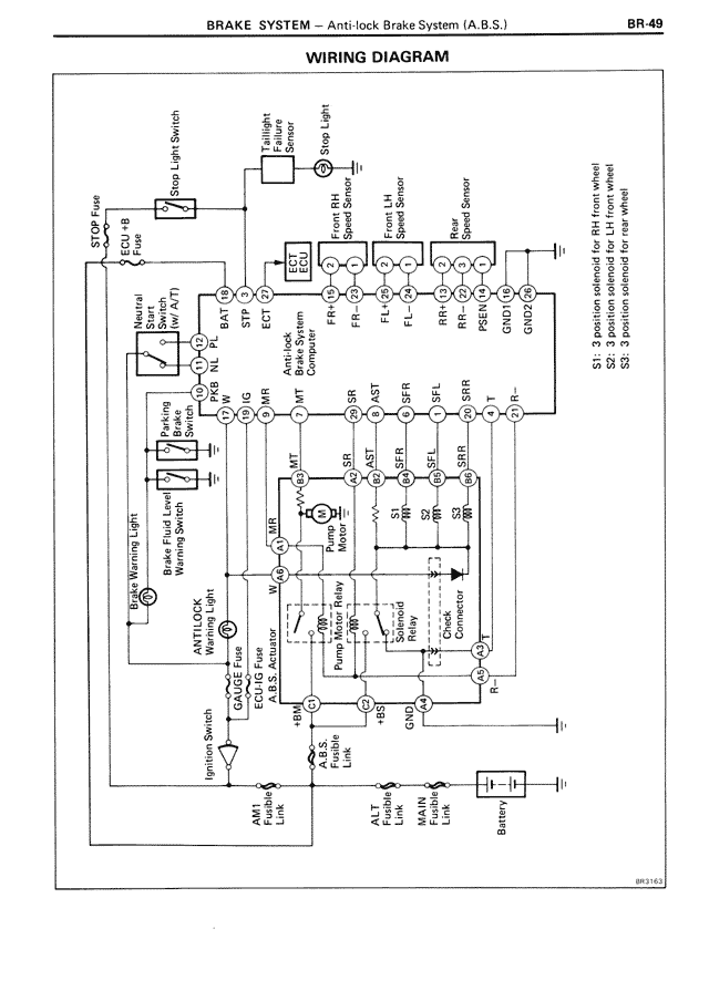
WIRING DIAGRAM
[This is a wiring diagram showing the Anti-lock Brake System circuit with the following labeled components and connections:]
SOL Fuse
CPU (B)
A.B.S. Fuse
Neutral Start Switch (A/T Only)
Stop Light Switch
Engine Fusible Link
E.C.U.
Brake Fluid Level Warning Switch
ANTI-LOCK Warning Light
BRAKE Warning Light
Ignition Switch
AM Fusible Link
A.L.T Fusible Link
A.MAIN Fusible Link
Battery
Diagram shows connections to:
- Front Solenoid
- Front RH Speed Sensor
- Front LH Speed Sensor
- Rear LH Speed Sensor
- Rear RH Speed Sensor
With notations:
S1: 3-position solenoid for RH front wheel
S2: 3-position solenoid for LH front wheel
S3: 3-position solenoid for rear wheel
Various wire connections labeled with codes including:
BAT, STP, IGT
MT, FR+, FR-, FL-, FL+, RR-, RR+, RSSR, PSIG, GND
BR37E3