100%
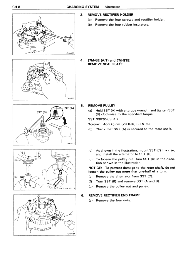
3. REMOVE RECTIFIER HOLDER
(a) Remove the four screws and rectifier holder.
(b) Remove the four rubber insulators.
4. [7M-GE (A/T) and 7M-GTE]
REMOVE SEAL PLATE
5. REMOVE PULLEY
(a) Hold SST (A) with a torque wrench, and tighten SST (B) clockwise to the specified torque.
SST 09820-63010
Torque: 400 kg-cm (29 ft-lb, 39 N-m)
(b) Check that SST (A) is secured to the rotor shaft.
(c) As shown in the illustration, mount SST (C) in a vise, and install the alternator to SST (C).
(d) To loosen the pulley nut, turn SST (A) in the direction shown in the illustration.
NOTICE: To prevent damage to the rotor shaft, do not loosen the pulley nut more that one half of a turn.
(e) Remove the alternator from SST (C).
(f) Turn SST (B) and remove SST (A and B).
(g) Remove the pulley nut and pulley.
6. REMOVE RECTIFIER END FRAME
(a) Remove the four nuts.