Page text (OCR transcript)
MANUAL TRANSMISSION — Component Parts (Output Shaft Assembly)     MT-23

[Diagram showing 3rd, 2nd, 1st gears]
F08J35

[Diagram showing measurement of gears with 3rd, 2nd, 1st labels]
F08J22

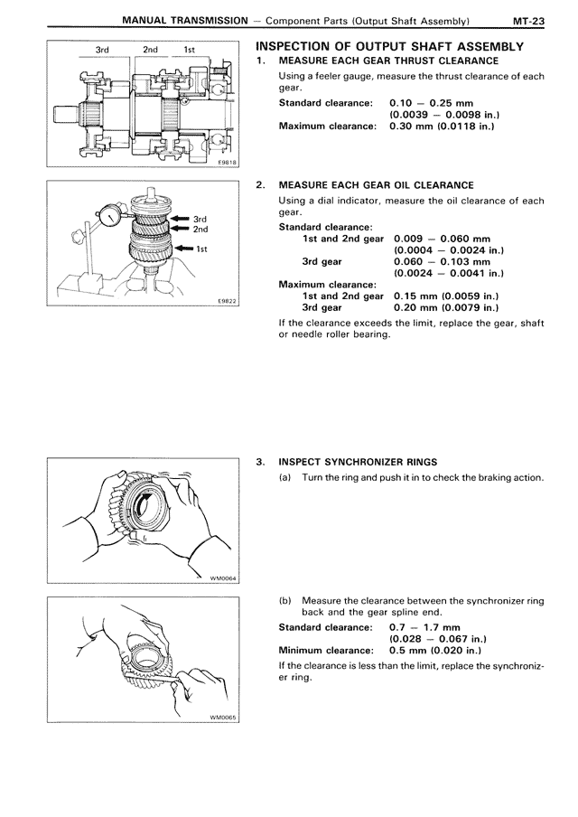
INSPECTION OF OUTPUT SHAFT ASSEMBLY
1. MEASURE EACH GEAR THRUST CLEARANCE
   Using a feeler gauge, measure the thrust clearance of each
   gear.
   Standard clearance:    0.10 — 0.25 mm
                         (0.0039 — 0.0098 in.)
   Maximum clearance:    0.30 mm (0.0118 in.)

2. MEASURE EACH GEAR OIL CLEARANCE
   Using a dial indicator, measure the oil clearance of each
   gear.
   Standard clearance:
      1st and 2nd gear  0.009 — 0.060 mm
                       (0.0004 — 0.0024 in.)
      3rd gear         0.060 — 0.103 mm
                       (0.0024 — 0.0041 in.)
   Maximum clearance:
      1st and 2nd gear  0.15 mm (0.0059 in.)
      3rd gear          0.20 mm (0.0079 in.)
   If the clearance exceeds the limit, replace the gear, shaft
   or needle roller bearing.

[Diagram showing hands inspecting synchronizer ring]
WA00064

[Diagram showing measurement of synchronizer ring]
WA00065

3. INSPECT SYNCHRONIZER RINGS
   (a)  Turn the ring and push to check the braking action.

   (b)  Measure the clearance between the synchronizer ring
        back and the gear spline end.
   Standard clearance:   0.7 — 1.7 mm
                        (0.028 — 0.067 in.)
   Minimum clearance:    0.5 mm (0.020 in.)
   If the clearance is less than the limit, replace the synchroniz-
   er ring.