100%
AT1–27
AT340E (2JZ–GE) AUTOMATIC TRANSMISSION – ASSEMBLY REMOVAL AND INSTALLATION
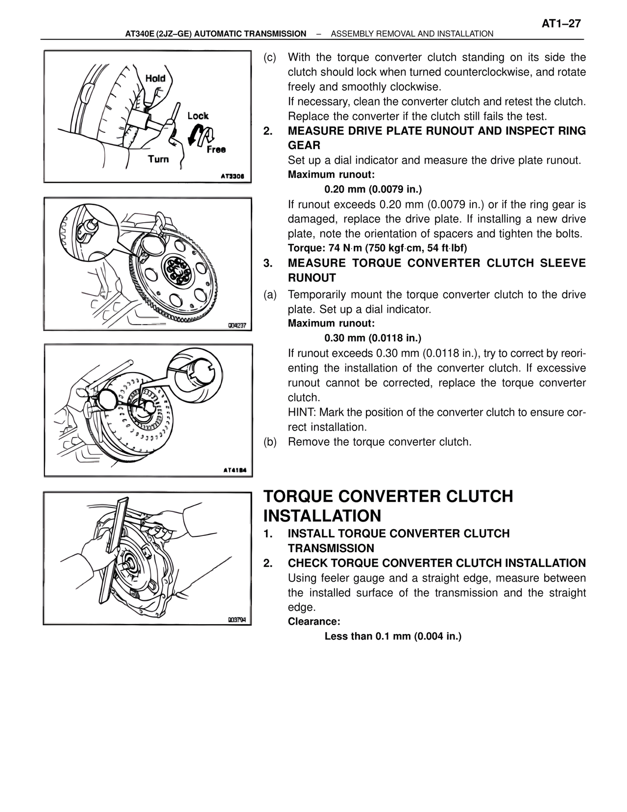
Hold
Lock
Turn
Free
AT3308
(c) With the torque converter clutch standing on its side the clutch should lock when turned counterclockwise, and rotate freely and smoothly clockwise.
If necessary, clean the converter clutch and retest the clutch. Replace the converter if the clutch still fails the test.
2. MEASURE DRIVE PLATE RUNOUT AND INSPECT RING GEAR
Set up a dial indicator and measure the drive plate runout.
Maximum runout:
0.20 mm (0.0079 in.)
If runout exceeds 0.20 mm (0.0079 in.) or if the ring gear is damaged, replace the drive plate. If installing a new drive plate, note the orientation of spacers and tighten the bolts.
Torque: 74 N·m (750 kgf·cm, 54 ft·lbf)
Q04237
3. MEASURE TORQUE CONVERTER CLUTCH SLEEVE RUNOUT
(a) Temporarily mount the torque converter clutch to the drive plate. Set up a dial indicator.
Maximum runout:
0.30 mm (0.0118 in.)
If runout exceeds 0.30 mm (0.0118 in.), try to correct by reorienting the installation of the converter clutch. If excessive runout cannot be corrected, replace the torque converter clutch.
HINT: Mark the position of the converter clutch to ensure correct installation.
(b) Remove the torque converter clutch.
AT4184
TORQUE CONVERTER CLUTCH INSTALLATION
1. INSTALL TORQUE CONVERTER CLUTCH TRANSMISSION
2. CHECK TORQUE CONVERTER CLUTCH INSTALLATION
Using feeler gauge and a straight edge, measure between the installed surface of the transmission and the straight edge.
Clearance:
Less than 0.1 mm (0.004 in.)
Q03794