Page text (OCR transcript)
AT1-95
AT340E (2JZ-GE) AUTOMATIC TRANSMISSION – TROUBLESHOOTING

TT Terminal Circuit

CIRCUIT DESCRIPTION

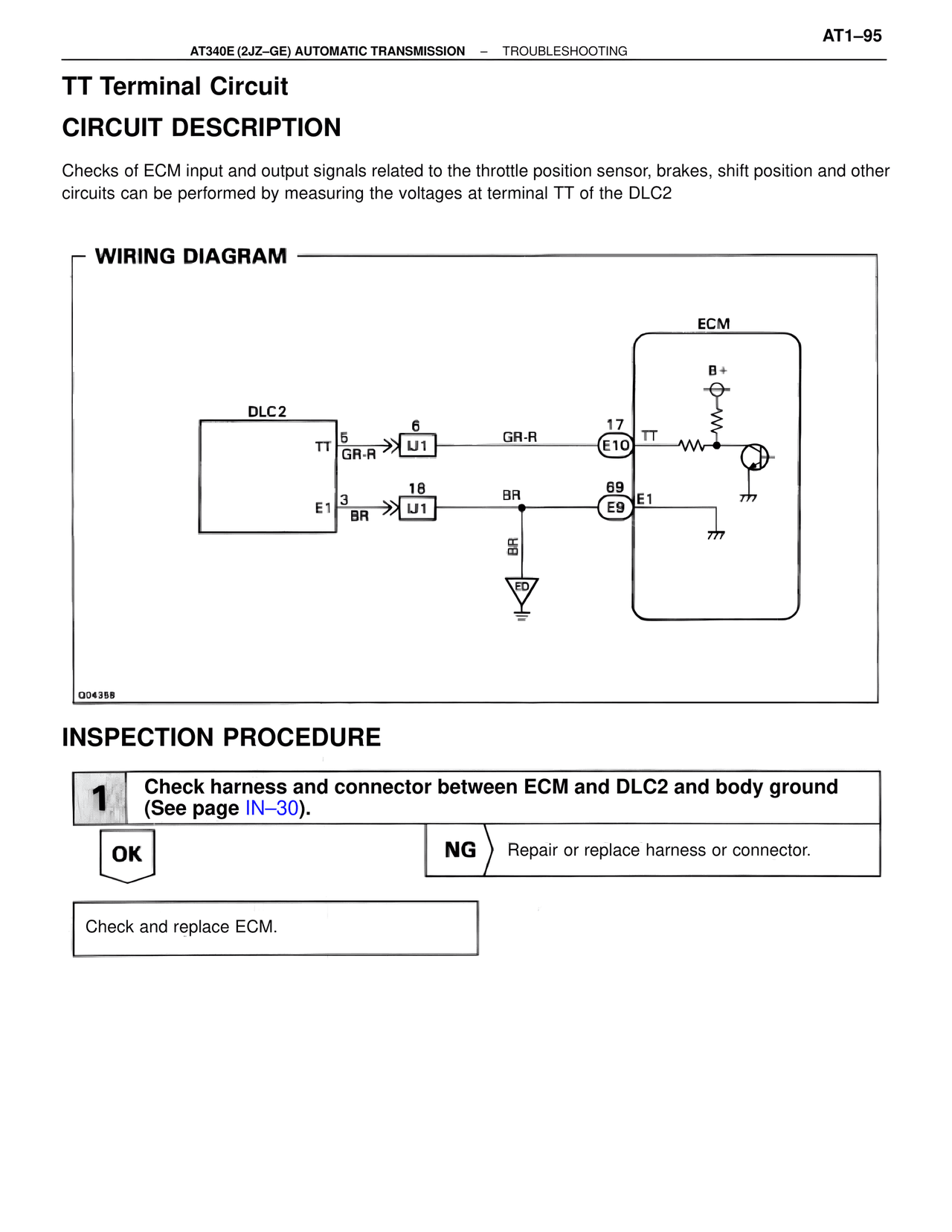
Checks of ECM input and output signals related to the throttle position sensor, brakes, shift position and other
circuits can be performed by measuring the voltages at terminal TT of the DLC2

WIRING DIAGRAM

DLC2

TT  5
GR-R

E1  3
BR

6
LJ1

18
LJ1

GR-R

BR

BR

ED

17
E10  TT

69
E9  E1

ECM

B+

Q04358

INSPECTION PROCEDURE

1  Check harness and connector between ECM and DLC2 and body ground
(See page IN-30).

OK

NG  Repair or replace harness or connector.

Check and replace ECM.